Planning – step by step to your own home irrigation system
To implement your own garden irrigation, I recommend going through the following planning steps in the order given:
First a short explanation of the basic functionality of an irrigation system:
Understand the basic principle of an irrigation system
The basis of any further planning is to understand the basic functionality of an irrigation system. This basically consists of 3 parts:
- Water source
- Water pipeline
- Sprinkler/Sprayer or other irrigation components
- optional: control device
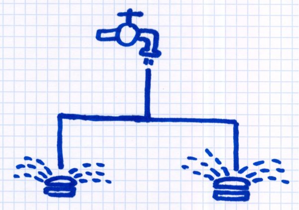
The water source supplies the irrigation system with the necessary water. This can be a tap or a well with an attached well pump. The pipeline consists of pipes that bring the water to the consumer components. These can be sprinklers, sprayers, a drip hose, a water socket, etc. The irrigation can be automated with an optional control device.
This explains the basic principle: water is fed into the pipeline, this flows via the pipeline to the distribution points and is used there for irrigation.
1. Determination of water volume and water pressure
This point is placed in front because it represents the prerequisite for all further considerations and can also make automatic irrigation impossible from the start. Why? The irrigation sprinklers require a certain minimum amount of water and a certain minimum water pressure in order to function. If the pressure is too low, the sprinklers do not rise at all or do not reach the intended throwing radius.
The amount of water present can be determined very easily with a so-called bucket test, which measures how long it takes to fill a 5 gallon water bucket.
The water pressure can be roughly researched as follows:
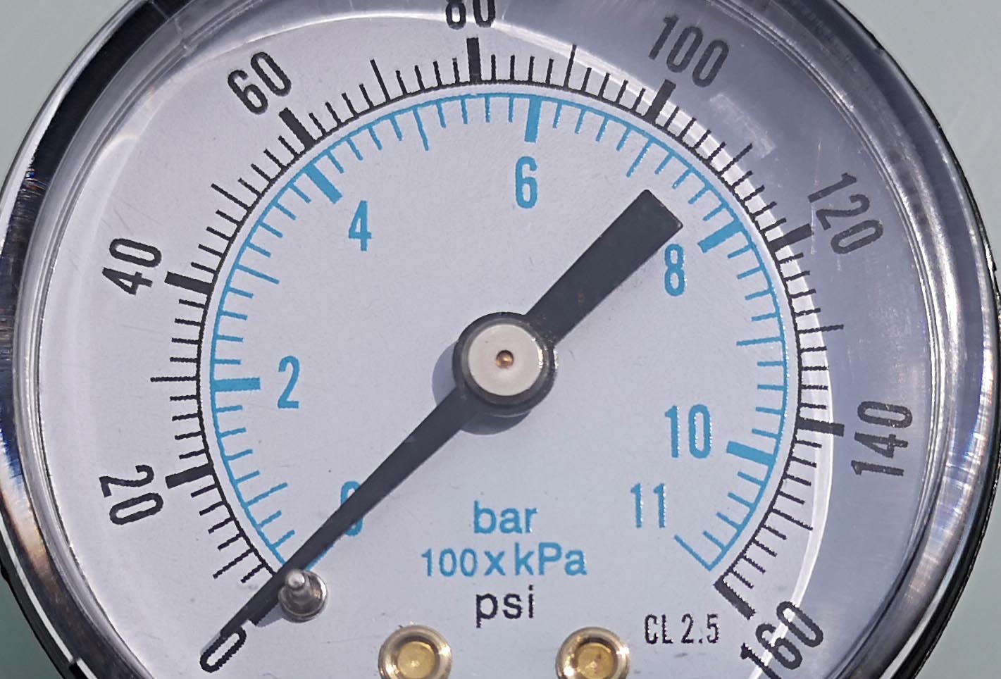
- When watering with water from the water pipe, ask the local water supplier. This introduces the water into the houses with a certain pressure as standard. If a manometer is installed at the connection of the house to the public water network, the pressure can be read there.
- When using a well pump, the pressure on the pump or in the description of the pump should be stated.
Both variants are only approximations that give you a first clue. An exact value can be obtained by measuring at the tapping point using a water pressure gauge (Amazon link). These are handy pressure gauges that are simply screwed onto the tap or the pump outlet and measure the pressure on them (static water pressure). When measuring on the water pipe, the pressure will be lower than the static pressure specified by the water supplier. This is because there are still pipes in the house between the house’s water connection to the public pipe and the tapping point, through which the water must flow and which consequently reduce the water pressure. Below are a few examples of water pressure gauges on Amazon:
Auto Amazon Links: No products found.
Important: During the measurement at the tap, no other water consumer may be in operation in the house, e.g. not. the washing machine or shower is running. The pressure measured at the tapping point is greater than the pressure that is actually available at the sprinklers, as there are friction losses in the pipe connections up to the sprinklers. The amount of water measured in the bucket test is also greater than that which will actually flow through the pipeline. Detailed information on this in Chapter 4!
At this point, it is sufficient for us to first check whether the water point is in principle suitable for operating an irrigation system. The Gardena company specifies a limit of 57 seconds for the bucket test that it can take to fill a 5 gallon bucket. The manufacturer often mentions a minimum pressure of 58 psi at the water extraction point, so that even sprinklers with a large water throughput can function without any problems. Rain Bird names a pressure between 40 and 60 psi as the ideal pressure that should be present at the water extraction point. Other manufacturers define a minimum pressure of 30 or 36 psi that must reach their sprinklers in order for them to work properly, more on this in Chapter 4.
Tip: If you have a value of around 38 seconds or less in the bucket test for a 5 gallon bucket, then you are definitely in the green area. The pressure measured at the tap should be at least 50 to 58 psi, a garden pump should have a delivery pressure of at least 58, better 65 psi. If the value is a little worse, an irrigation system can still be implemented with coordinated planning (division into more sectors, use of sprinklers that work with lower water pressure). More on this in the following chapters.
2. Create a sketch of the garden
As a basis for planning, it is advisable to create a true-to-scale plan of the object to be watered on graph paper. For example, if the garden is 51 feet wide, then 3 feet might correspond to one square on the plan. The total 51 feet width therefore make 17 squares on the graph paper. Alternatively, you can also use an existing property plan as a basis for further planning.
The plan should also show which plant species appear on which part of the plan, as different plants require different irrigation. It should also be clear from the plan which parts of the garden should not be watered. So the plan is intended to answer questions like the following:
- Where is the lawn located?
- From where to where does the hedge run?
- Where are larger shrubs or trees or also firmly anchored play equipment?
- Where is the vegetable patch?
- Are there plant pots or plant troughs that should be included in the irrigation?
- Which part are stone slabs / wooden terrace or other parts that should not be watered? Where do you have to be careful not to splash onto the neighboring property?
This can be sketched very quickly by hand, as in the following example:

Example of a sketch created manually in 2 minutes with a rough planning of the different areas
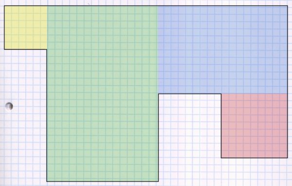
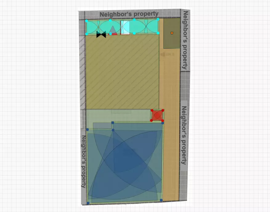
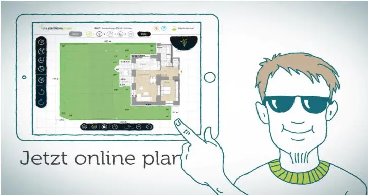
Or you can do a little more work and create the plan with the help of a graphics program on the computer. Above all, this has the advantage that rescheduling can be carried out very easily; with a hand-drawn plan, it soon becomes illegible after repeated corrections. Below is an example of a plan made using a graphics program:

In this case, there would be a large continuous lawn and an additional smaller strip of lawn behind the house. In the lawn, the recorded tree is essential because it is an obstacle to watering and must therefore be taken into account when planning. In addition to the lawn, there is also a vegetable patch here, which has completely different requirements than the lawn, since irrigation with rain would be far too “brutal” and would wash out the earth. And last but not least, a thuja hedge and various plant pots and boxes, which also have their own requirements. This rough knowledge of the different requirements is the starting point for the next point:
3. Getting to know the basic irrigation systems and the difference between sprinklers, sprayers, emitters, etc.
In order to decide which means to use for irrigation, a basic knowledge of the various systems offered and how they differ is necessary. The garden irrigation can be divided into the following two major areas:
- Lawn Irrigation
- Drip Irrigation
Lawn irrigation is used for larger, contiguous areas, while drip irrigation is well suited for irrigation of narrow or uneven terrain. An essential difference is the necessary water pressure: drip irrigation systems require a significantly lower initial water pressure of around 22 psi, for lawn irrigation at least 50 to 58 psi should be available. Drip irrigation is therefore also a possible alternative if there is not enough water pressure, but it is often used together with lawn irrigation, e.g. the lawn is irrigated with lawn irrigation, bushes and vegetable patches with drip irrigation.
This is followed by a description of the two irrigation systems:
Lawn Irrigation
Lawn irrigation is laid underground. Normally it works with sprinklers sunk into the ground, which only rise when the irrigation is carried out, otherwise they are practically invisible and do not stand around in a disturbing way. A distinction is made between two types of sprinklers based on how they work:
- Rotating sprinklers (geared sprinklers)
- Nozzle sprinkler (sprayer)
-
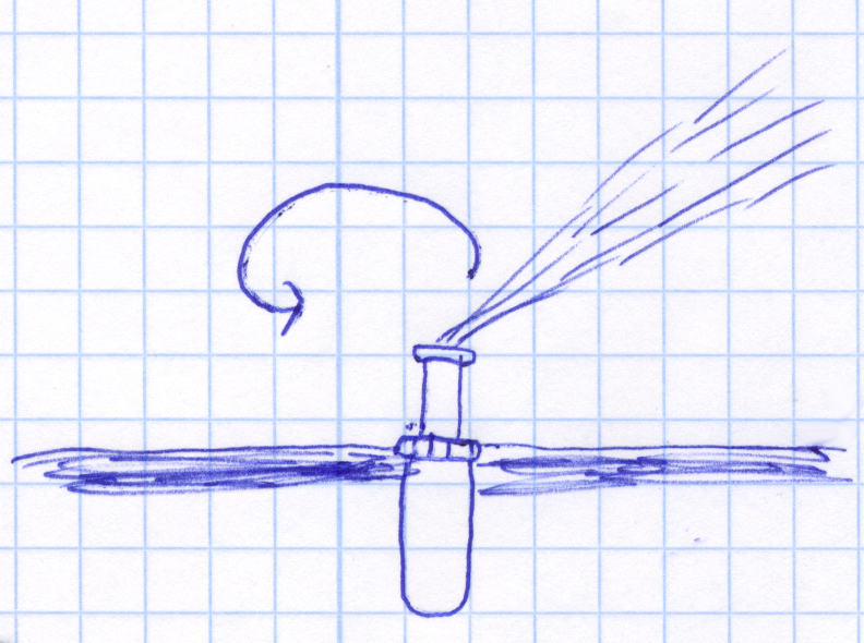
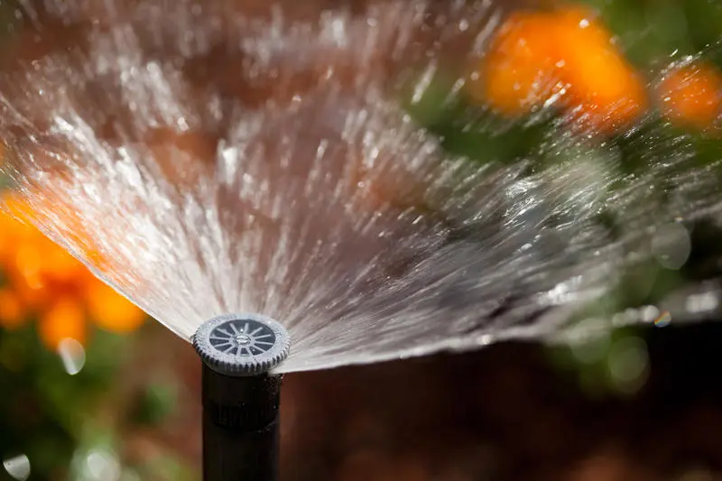
- Example of a rotating sprinkler
-
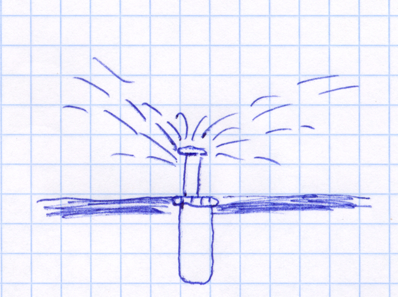
- Example of a nozzle sprinkler (sprayer)
The difference is easy to explain: The rotating sprinkler (also known as a geared sprinkler) releases the water in a concentrated jet and slowly rotates around its own axis. A nozzle sprinkler, on the other hand, works more like a shower head, which emits the water in one gush in many directions at the same time.
Due to the concentrated water release, the rotating sprinkler can achieve very large throwing distances of up to 65 feet, while short distances of less than approx. 13 feet are not possible at all. The nozzle sprinkler, on the other hand, only works for distances of up to approx. 16 feet.
The whole thing is also available as a mixed form: Nozzle-sprinkler, whose nozzle on top rotates. The water is no longer released in a gush, but the gush is divided into many small water jets, which are continuously released at different points by the rotation of the nozzle. The advantage is a significant water saving compared to the usual nozzle sprinkler. This can be a great advantage if you have little water available or if you don’t want to split the pipeline into too many sectors. In addition, higher throwing distances are possible than with normal nozzle sprinklers, namely up to 32 feet. Representatives of this genus are the MP Rotator from Hunter and Rain Bird R-VAN.
When do you use rotating sprinklers and when do you use nozzle sprinklers?
Here you can orientate yourself on the following points, which should be valid in most cases:
- Is the area to be watered larger than 32 x 32 feet? -> Rotating sprinklers
- Is the area smaller or also long and narrow (10 to 26 feet wide?) -> nozzle sprinkler
- If you have less than 58 psi (at the water extraction point) available -> nozzle sprinkler
- If the area to be watered has sharp corners and it is important that the adjacent area is not watered -> nozzle sprinkler
The rotating nozzle sprinklers combine advantages from both worlds and are in principle suitable for all 4 cases mentioned.
Drip irrigation
Drip irrigation systems are usually installed above ground and are used to irrigate smaller or non-contiguous or uneven areas, but also to irrigate areas that should not be watered with hard water jets but rather gently. There are two types of drip irrigation:
- Micro Sprayers
- Drip Tubing/Drip Emitters
Micro Sprayers do not pour gushingly, but spray the smallest water droplets. In contrast to lawn irrigation, they do not extend out of the ground, but are fixed above ground. Drib tubes are placed above ground in hedges or bushes. At a distance of a few centimeters, the water slowly drips out of the tube and is released directly and water-saving (less evaporation) on the surface of the earth. Since the water pressure used in drip irrigation is comparatively low (usually between 22 and 26 psi), the range of the sprayers is small. These must therefore be set at a small distance from one another.
Typical uses of drip irrigation: flower and vegetable beds, hedges, shrubs, flower pots and boxes, irrigation on balconies, plants in uneven terrain
So you could say that drip irrigation is responsible for the fine-tuning. Where there are no large coherent areas, or where lawn irrigation, e.g. due to uneven terrain, cannot be properly adjusted, it is too “coarse” or too little finely adjustable (irrigation radius would irrigate large areas that are not irrigated would like) drip irrigation is used. It is therefore often used in addition to lawn irrigation. And it is also used on a large scale, e.g. for watering bushes and shrubs in large parks.
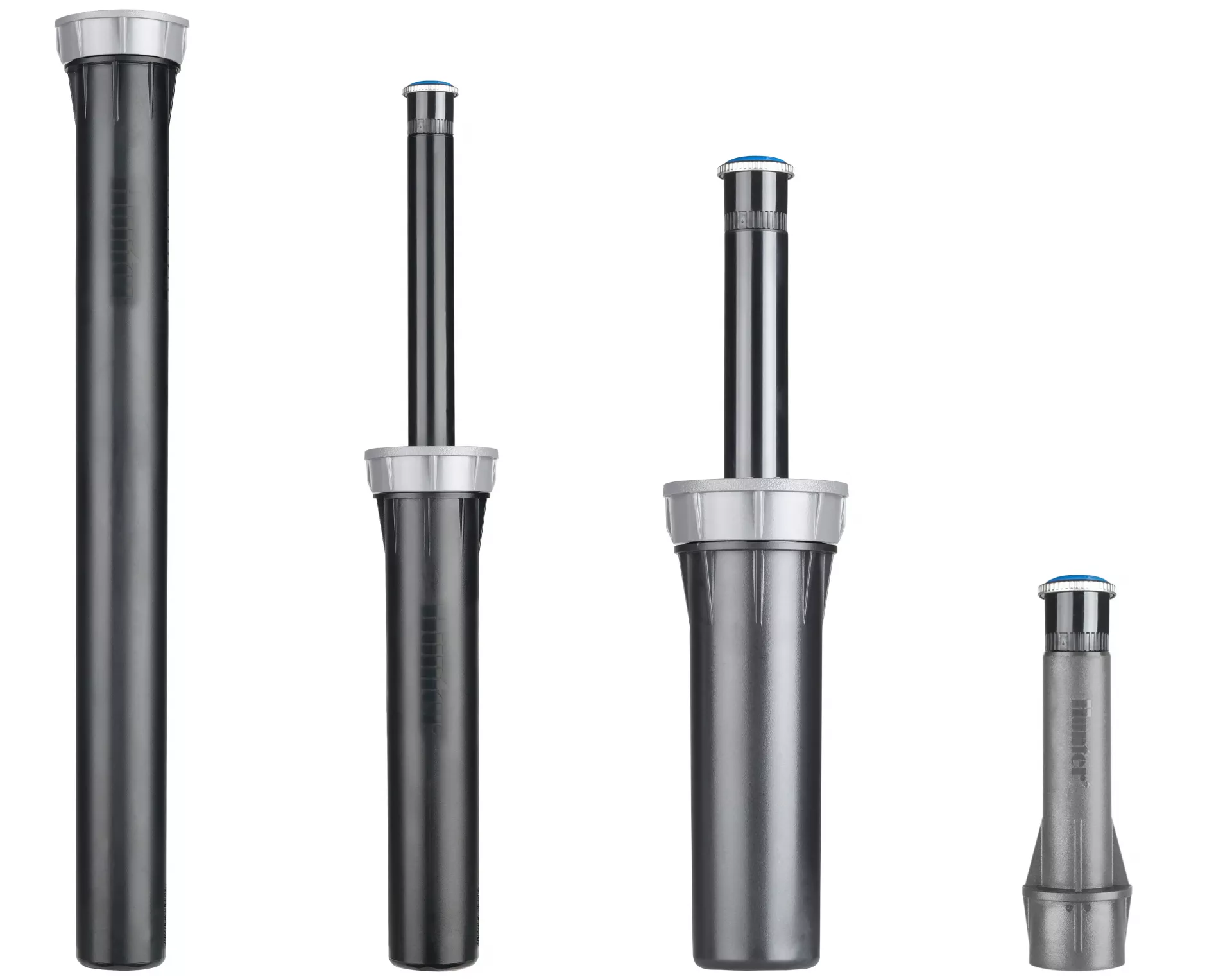
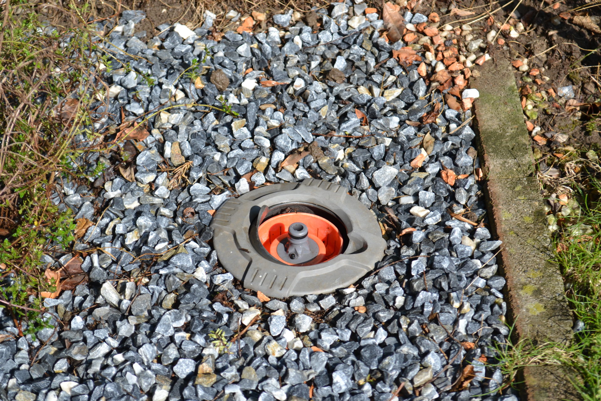
Retractable or fixed?
Pop-up sprinklers are usually used in lawn irrigation. These are sprinklers that are installed at ground level and rise when the irrigation starts due to the water pressure. When the irrigation is over, they automatically retract. Otherwise they are practically invisible and the irrigated area can be used without restrictions, e.g. football can be played on it. Fixed sprayers without a lowering mechanism are mainly used in drip irrigation. Since this type of irrigation is installed above ground and mostly on areas that are not or only rarely walked on, lowering is not necessary here on the one hand and the fixed and mostly higher installation is an advantage when watering higher-growing plants. Fixed sprinklers are rarely used on lawns, apart from the visual aspect, they also pose a risk of injury from accidentally getting stuck.
The risers are available in different heights, the most commonly offered heights are 2, 4, 6 and 12 inches.
My tip: 2 inch risers are generally not a good idea! Even recently mowed grass can become a problem here and interfere with the correct functioning of the sprinkler. Better to use 4 inch or 6 inch risers. If the sprinkler is surrounded by bushes or taller plants, the 12 inch or even higher risers are ideal.
All sprinklers of the same brand / model or mix?
In principle, it is not a problem at all and it is also quite common to use sprinklers from different manufacturers and different models within an irrigation system. So you can fall back on the most suitable product for every task. However, the following golden rule must be observed:
Never mix nozzle sprinklers and rotating sprinklers!
The reason is the very different amount of water that is released in a certain period of time. Nozzle sprinklers, for example, deliver around four times the amount of water to their sector to be irrigated in the same time as rotating sprinklers. If the irrigation duration were based on the nozzle sprinklers, the area around the rotating sprinklers would receive far too little water and the lawn would dry out. If you adjust the irrigation time to the rotating sprinkler, the area around the nozzle sprinkler becomes muddy due to the overwatering and waterlogging occurs. That being said, wasting water in this way would not be beneficial to your wallet or the environment. Therefore: Never mix rotating sprinklers with nozzle sprinklers!
And ideally, the second rule is also followed:
It is best to have only one brand and one sprinkler model per sector!
The difference here is usually not as great as when mixing nozzle sprinklers and rotating sprinklers, but different sprinkler models within the same type of sprinkler can also have very different amounts of precipitation. If you mix these you should be careful to combine sprinklers with as similar amounts of precipitation as possible.
What is cheaper in terms of price?
From a cost perspective, it doesn’t really matter whether you use rotating sprinklers or nozzle sprinklers. The rotating sprinklers are significantly more expensive to purchase per sprinkler, but in return they also cover a larger area. And with nozzle sprinklers, there are higher costs for additional pipe connections and couplings due to the larger number of sprinklers required.
Advantage of stainless steel sprinklers?
With some of the sprinkler models on offer there is the option of buying a stainless steel version instead of the usual plastic version. In this case, part of the sprinkler, the riser, is made of stainless steel instead of plastic. The stainless steel version costs on average 30 to 40% more than the plastic version. This is mainly advertised with the argument of an even longer shelf life.
My Opinion: It’s a luxury that you don’t have to afford. Plastic sprinklers from good suppliers also have a very long shelf life. And I am also not aware of any studies or long-term observations that confirm this alleged longer shelf life. The longer shelf life also seems only to a limited extent logical, since only part of the sprinkler is made of stainless steel, but the rest of it is still made of plastic. Stainless steel sprinklers undoubtedly provide a certain wow factor: If you want to shine with something unusual in the garden and earn admiring glances from your neighbors, then they are definitely worth considering. For purely rational reasons, however, there is very little to be said for it in my opinion.
4. Determine the pressure loss in the pipeline and the water flow
This point may be surprising at first sight and appear twice with the 1st point. Hasn’t the available amount of water and the available water pressure already been measured there? To understand this, it is important to know the difference between the following three metrics:
- Static water pressure directly at the water source
- Dynamic water pressure in the pipeline
- Static water pressure in the pipeline
The static water pressure at the water source is what was measured in point 1. This is the pressure that is present directly at the water source, i.e. at the pump outlet or the tap, when the water flow rate is zero. However, this does not reach the sprinklers in full. On the one hand, this is due to factors such as friction in the pipeline, which reduce the pressure. This pressure loss must be calculated and subtracted in the first step. What then remains is the basis for the second step.
This is about the fact that the amount of water available at the water source is greater than the amount of water that actually flows through the pipeline and is poured over the sprinklers. This is due on the one hand to the pressure loss that has not yet been taken into account, but above all to the fact that the amount of water in point 1 was measured in such a way that the water could flow out without counter pressure. In a pipeline, however, the water not only has to flow straight through the pipes, it also has to exert a certain static pressure on the pipeline so that the sprinklers rise and pour. Most sprinklers, for example, require a minimum pressure of 22 psi.
The physical law applies: total pressure = static pressure + dynamic pressure. The static pressure in the pipeline can be thought of as the pressure that acts on the left and right of the pipe walls, the dynamic pressure as that which drives the water and acts forwards towards the pipe outlet. If the water were to be chased through the pipe with maximum dynamic pressure and therefore maximum flow speed, no or hardly any static pressure would be exerted on the pipe walls. You then have a very large amount of water, but the sprinklers don’t work. If you brake the dynamic pressure and thus the amount of water flowing through the pipeline, the static pressure on the pipe walls increases to the same extent and the pressure is generated that is necessary for the sprinkler to operate.
Then you will learn how to calculate the pressure loss and find the desired balance between the pressure required for the sprinklers and the water flow rate:
Determination of the water pressure loss in the pipeline
The static water pressure directly at the water source should already be known from point 1. This is decimated by various factors that lead to pressure losses in the pipeline.
Note: like any other mechanical system, an irrigation system needs energy to function. It draws this energy from the water pressure. For every meter that the water has to travel and every component that the water flows through, part of this energy is lost. You can imagine it like a car that uses gasoline for every kilometer traveled. The inlet water pressure must be high enough that after all the meters covered and the water pressure lost, the energy is still sufficient for the last sprinkler to pass through.
How much water pressure is lost in the pipeline depends on the length of the pipeline, the diameter of the pipe joint, and the amount of water that runs through the pipeline. Please see the following blog post for instructions on how to determine the water pressure drop in your pipeline.
Example:
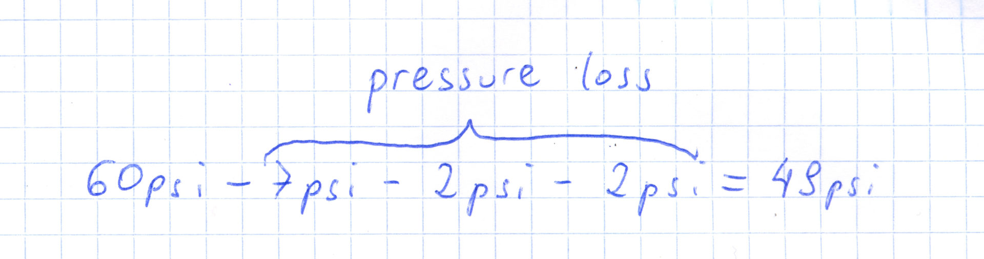
A pressure of 60 psi and an available water volume of 600 gallons were measured at the tap connection or the garden pump. The pipeline is divided into three irrigation sectors. Sector A has a pipe length up to the furthest sprinkler of 100 feet, Sector B and C of 130 feet. Three T-pieces are installed in each sector.
-> In sector A the pressure loss due to the pipe length is 7.3 psi, the pressure loss due to the T-pieces is 1.5 psi. In Sector B and C the pressure loss due to the pipe length is 10.2 psi, due to the T-pieces there is also a pressure loss of 1.5 psi. Thus the pressure loss in sector A is 8.7 psi and in sectors B and C 11.6 psi. After subtracting the pressure loss, a water pressure of 51.3 psi is available in sector A, and a water pressure of 48.4 psi is available in sectors B and C.
Whereby these values are set generously, since they are calculated with the available amount of water. The actual amount of water flowing through the pipes during operation is actually relevant for the pressure loss and is significantly smaller than the amount of water available. With this conservative calculation you are always on the safe side.
In some cases there may be other components or factors that consume water pressure and must therefore be subtracted from the available water pressure:
- The pipeline has to overcome an incline -> If the garden is not level and the water connection is lower than the sprinkler, then 1.5 psi pressure loss must be deducted for every 3 feet of increase in altitude. Note: Conversely, a gradient would lead to a pressure increase of 1.5 psi per 3 feet of depth.
- The pipeline runs through a water meter (approx. 1.5 to 3 psi deduction)
The pipeline goes through a check valve (approx. 1.5 to 4.5 psi deduction)
The pipeline runs through a solenoid valve (approx. 1.5 to 4.5 psi deduction)
The values for the water meter, check valve and solenoid valve are only approximate values. If the flow rate is small, the lower value is more likely to apply; if the flow rate is high, the higher value. Detailed information on pressure loss can be found in the manufacturer’s information, where the pressure loss for certain water volumes is usually listed in a table. There are also pressure losses when using components such as water distributors.
In our example, all three sectors pass through a solenoid valve. With the existing flow rate, the pressure loss is an estimated 1.5 psi.
This ultimately leaves a remaining water pressure of 49.8 psi in Sector A and 46.9 psi in Sector B and C. The pressure loss in sector A is 11.2 psi and in sectors B and C 13.1 psi.
Determination of the actual amount of water flowing through the pipeline
In point 1 you have already calculated the amount of water that is directly available at the water source (tap or well pump) with a bucket test. This is released from the water source when there is no resistance to overcome, i.e. the water has free flow. So with zero pressure that the water has to exert. In order for the irrigation to work, i.e. for the sprinklers to extend and start watering, they need a certain water pressure to act on them (static pressure that acts on the outer walls of the pipe in the pipeline). This static water pressure has to be built up in the pipeline by reducing the dynamic water pressure (= by braking the water) and consequently has a negative effect on the amount of water flowing through. Experts say that in an irrigation system around 70% of the amount of water measured in the bucket test is actually available for irrigation, i.e. it flows through the pipeline.
Note: The static (acting on the outer walls of the pipe) and dynamic (ensuring the flow velocity in the pipe) pressure in the pipeline are opposing factors that together give the total pressure. An increase in one to a certain extent means a reduction in the other to the same extent and vice versa.
The following relationship applies: the higher the water pressure requirement of the sprinkler and thus the static water pressure to be built up in the pipeline, the lower the dynamic pressure and thus the flow speed and the less water flows through the pipeline. So if you let the water run through a pipeline with no sprinklers and let it out through the pipe at the end of the pipeline, then almost all of the water measured at the water source would arrive. Only the previously measured water pressure loss in the pipeline pipes, for height increases or when passing through T-pieces and valves would have a negative effect. The water loses pressure to overcome these obstacles and pays for it with the amount of water passing through.
If a pressure of 30 psi is exerted on the sprinklers in the pipeline, more water will run through the pipeline than if 35 psi or 40 psi pressure is exerted on the sprinklers. Every increase in the total pressure requirement of the pipeline (pressure requirement of the sprinklers including the calculated pressure loss in the pipeline) has an inversely proportional effect on the amount of water flowing through. When shown graphically, this results in a curve as shown below:
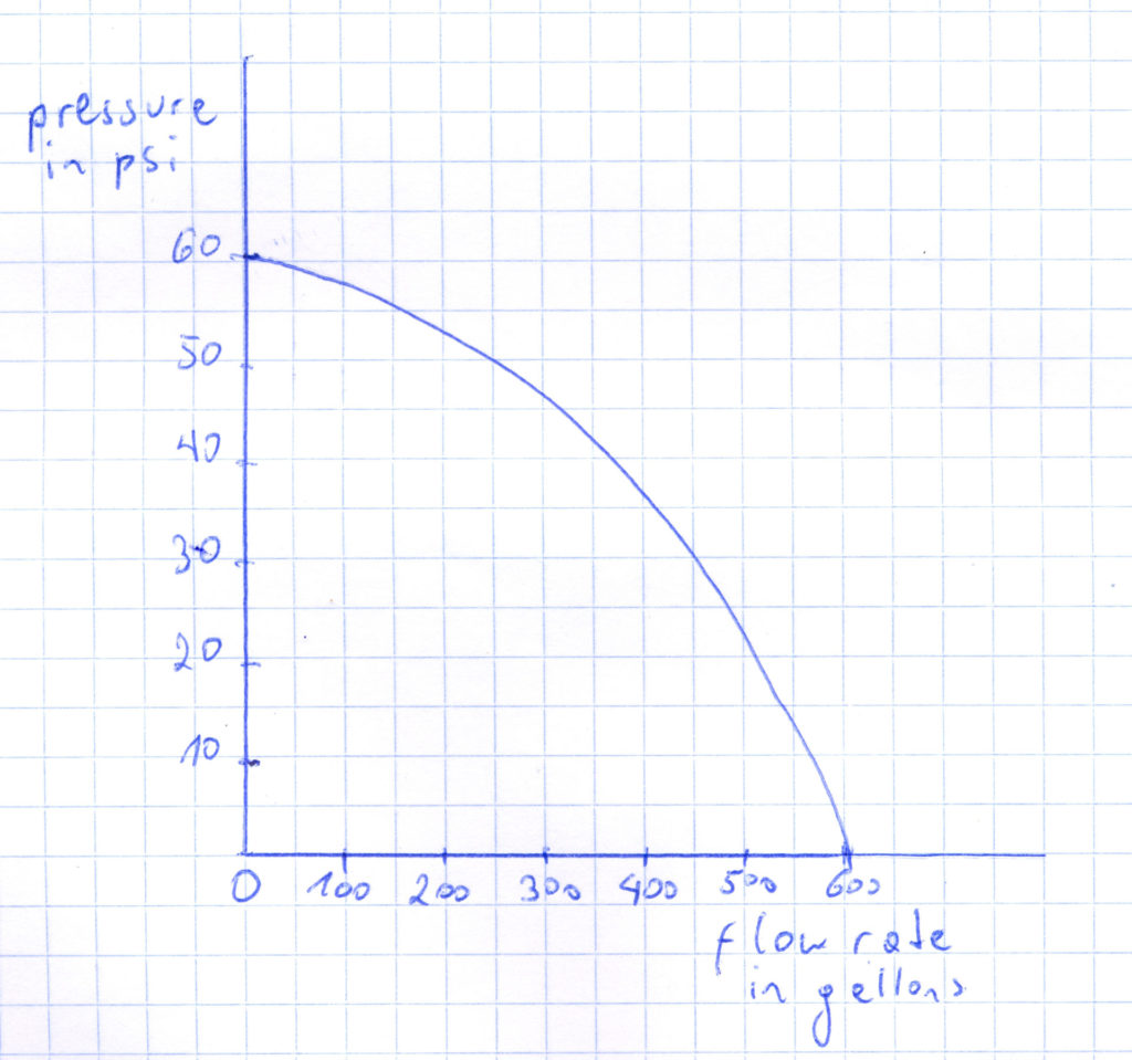
Example of a pump curve
The diagram shows the relationship for the example given above. In this the static water pressure at the water source is 60 psi. At 60 psi, no water flows (0 gallons). The amount of water measured at the water source with zero resistance is 600 gallons. According to this, the flow rate at 0 psi is 600 gallons. A water pressure and flow test gauge is required to determine the values in between. This is a device that outputs the resulting flow rate for every water pressure. Below is an example of such a device:
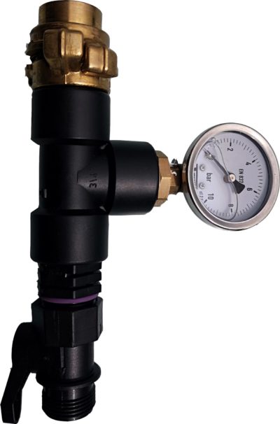
Water pressure and flow test gauge
The device is offered in two different versions:
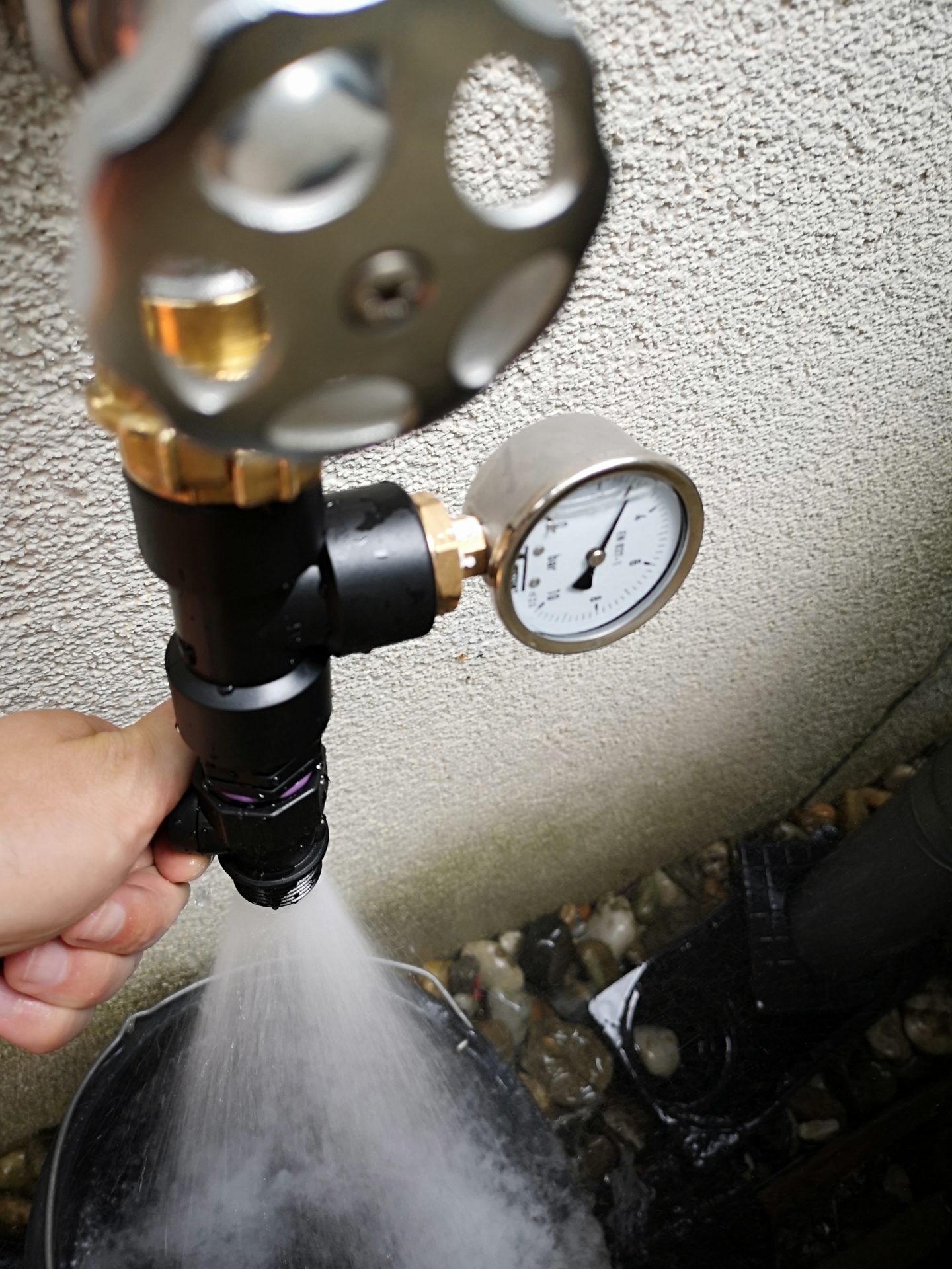
One – to which the pictured model belongs – consists of a tube that is open at the top and bottom and to which a water manometer is screwed to the side. In the lower area there is a rotary handle with which you can gradually open or close the valve built into the pipe. How to use: You screw the device to the tap or another water source, turn the tap on fully and close the valve until the water manometer shows the desired pressure, e.g. 40 psi. Note: You reduce the dynamic pressure by slowing down the water and thus increase the static pressure acting on the sides. Now, when the desired pressure is displayed, place a bucket under the tester and do a bucket test. So you stop the time it takes to fill the bucket and calculate the gallon output per hour from this. In the following blog post you will find detailed instructions for using the water flow test device, including information on where it can be obtained.
The other variant works in exactly the same way, but has an additional pressure gauge integrated so that a bucket test is not necessary.
For example, the information has now been obtained from the measurements that with a static pressure of 40 psi in the pipeline and acting on the pipelines, a flow rate of 280 gallons would be available. If the pressure is only 30 psi – leaving more of the total pressure for the dynamic pressure that provides the flow rate, then you would have about 80 gallons more, 360 gallons. After you have noted the measurement results for different measurement points as described in the blog post, you now have all the information you need to carry out the sprinkler selection.
Note: If the water source is a pump, you can alternatively derive the amount of water at a certain water pressure from the pump curve.
Planning tips
Now that you are familiar with the basic irrigation systems and how they work, you can basically start drawing sprinklers, sprayers, micro-drip elements, etc. into your garden plan. Before that, just a few basic planning tips and information on the limits within which you should move when planning:
- Generally speaking, sprinklers irrigate in a circular pattern
Although sprinklers are occasionally available on the market that water a rectangular area, these systems are not very mature and do not work reliably. I do not recommend including such sprinklers in your planning, in principle you can achieve the same result with circular sprinklers. - A complete circle or part of a circle (circle segment) can be watered
However, the sub-area must have a certain minimum size, e.g. it is not possible to water a circle segment of only 10 degrees! Depending on the manufacturer, the smallest possible circle segment begins at approx. 25 degrees, the Hunter sprinklers from 40 degrees.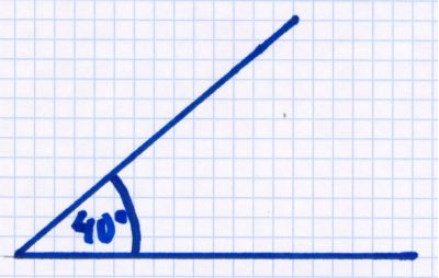
Most sprinklers require a minimum size of the circle segment to be irrigated of at least 40 degrees, even sharper circle segments are not possible.
- A sprinkler can throw a maximum of 65 feet
- The smallest rotating sprinklers have a minimum throw of about 13 feet
This means that smaller radii cannot be watered with it, as it would spray over them. - The smallest nozzle sprinklers have a minimum throw of about 5 feet
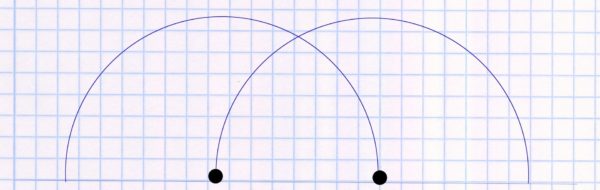
An exception to this rule are so-called “bubbler”, which can also throw distances of only 1 foot. - The throwing circles of the sprinklers must overlap 100%
This is the most common mistake, and professionals and even online planning tools often misrepresent it. The sprinklers hurl more water far away from them than they release in the immediate vicinity. As a result, the area directly around the sprinklers is undersupplied with water and must be supplied by another sprinkler. Therefore a 100% overlap of the throwing circles is necessary.
Example:
So it’s wrong! The throwing circle of one sprinkler just reaches the throwing circle of the other sprinkler.
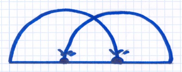
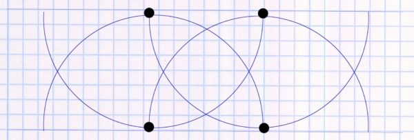
This is how it is done correctly: The throwing circle of one sprinkler reaches to the other sprinkler. The areas directly around the sprinkler are also watered by the other sprinkler.
6. Place sprinklers correctly – square pattern and triangle pattern
The first considerations for an irrigation system usually look like this:
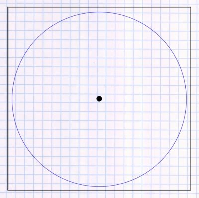
A single sprinkler that is placed in the middle of the garden and ideally you want to water the entire garden with it. If your considerations were similar, you will be very surprised at how many sprinklers you have to use for correct watering. In lawn irrigation, each area is watered with multiple overlaps. The main advantage of this is that there are really no dry spots that lead to brown spots in the lawn, but the lawn is watered evenly and thrives. The problem lies in the fact that the sprinklers only pour poorly in their immediate vicinity, i.e. the area close to the sprinkler gets comparatively little water. And on the other hand, the amount of precipitation is not absolutely uniform over the entire throwing area. These shortcomings must therefore be compensated for by other sprinklers. In addition, the principle “small is beautiful” applies to irrigation: the use of many smaller sprinklers – compared to a few large sprinklers – increases flexibility if the irrigation has to be rescheduled at a later date or there are still spots somewhere that haven’t yet fit perfectly.
Background: Planning as described below may look unnecessarily generous at first glance, but ultimately saves a lot of water thanks to even watering. If the lawn is watered unevenly, then the watering time must always be based on those areas that get the least water. Otherwise brown spots will appear. Poor planning means that you have to water a few minutes longer, even though the majority of the lawn would already have had enough water to supply the areas with a poorer water supply.
The most important principle is that the throw from one sprinkler must reach the other sprinkler (overlap):
And not just once, but twice! Not only does the throwing circle of the sprinkler placed next to it have to touch the next sprinkler, but also the throwing circle of the sprinkler on the opposite side has to reach the sprinkler!
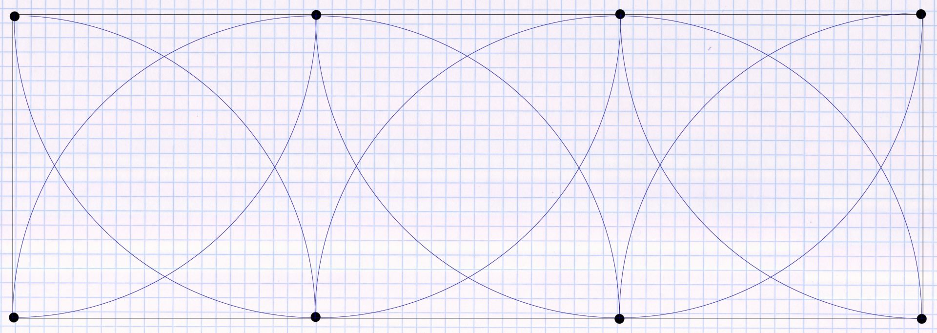
Before you start placing the sprinklers, the first step is to break down the entire sprinkling area into the largest possible squares. Illustrated with the example of the following garden:
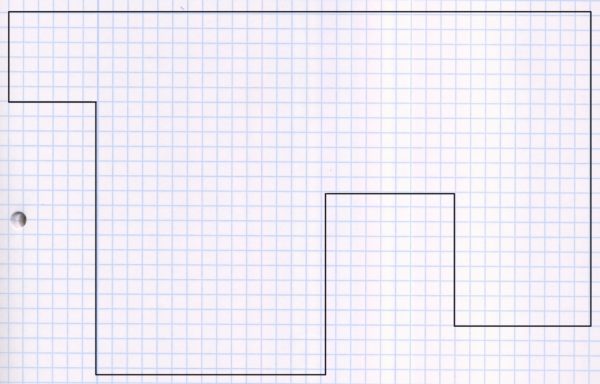
This could now be divided into the following 4 rectangles:
After the garden has been divided, the next step is how to place the sprinklers optimally. That depends on the shape of the rectangle. In a square, the sprinklers are placed in all 4 corners as follows:
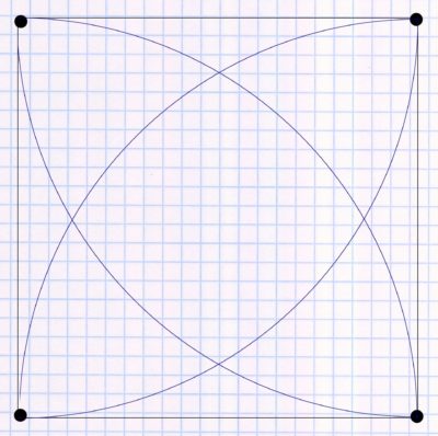
The throwing circle of all 4 sprinklers extends to the sprinkler to the left and right of it, so each of the sprinklers has a double overlap. The prerequisite for being able to implement this is that the throwing circle of the sprinklers is large enough to reach the sprinklers to the right and left of it.
However, if the area is rectangular, the procedure is as follows: First sprinklers are placed in the 4 corners.
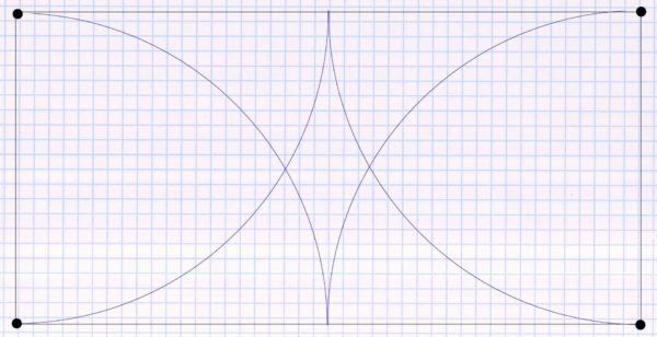
Here you can clearly see that an area in the middle remains unwatered for the time being and that the principle of double overlapping is no longer observed. Therefore, as many more sprinklers as necessary are now placed on the two longer sides. So many are necessary that the throwing circle of the additionally placed sprinklers reaches to the corner sprinklers and the additionally placed sprinklers are doubly overlapped. In the simplest case, if the aspect ratio of the rectangle is 2 to 1, e.g. 60 by 30 feet, an additional sprinkler is placed in the middle of the long side for each long side:
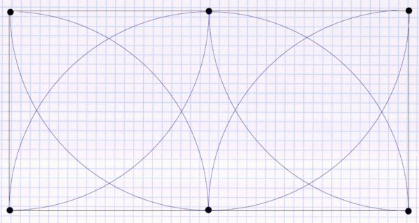
If the longer side is larger, e.g. with an aspect ratio of 90 by 30 feet, then additional sprinklers must be used on each long side. It is important that each sprinkler from the throwing circle is still reached by two other sprinklers. If, for example, two additional sprinklers are placed on each long side, as in the example below, the throw of these two sprinklers must reach the nearest corner point and the sprinkler placed next to it on the long side. It then looks like this:
If the width of the rectangle is greater than the maximum range of the sprinklers used, so that the throwing circle no longer reaches to the opposite sprinkler, then an additional row of sprinklers must be placed in the middle (example 90 by 60 feet):
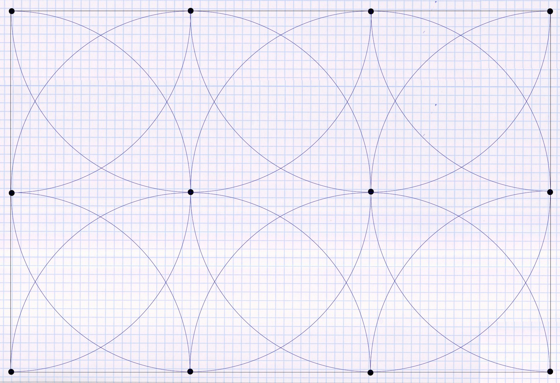
4 additional sprinklers were placed in the middle. The two on the edge throw semicircles, the two inside full circles.
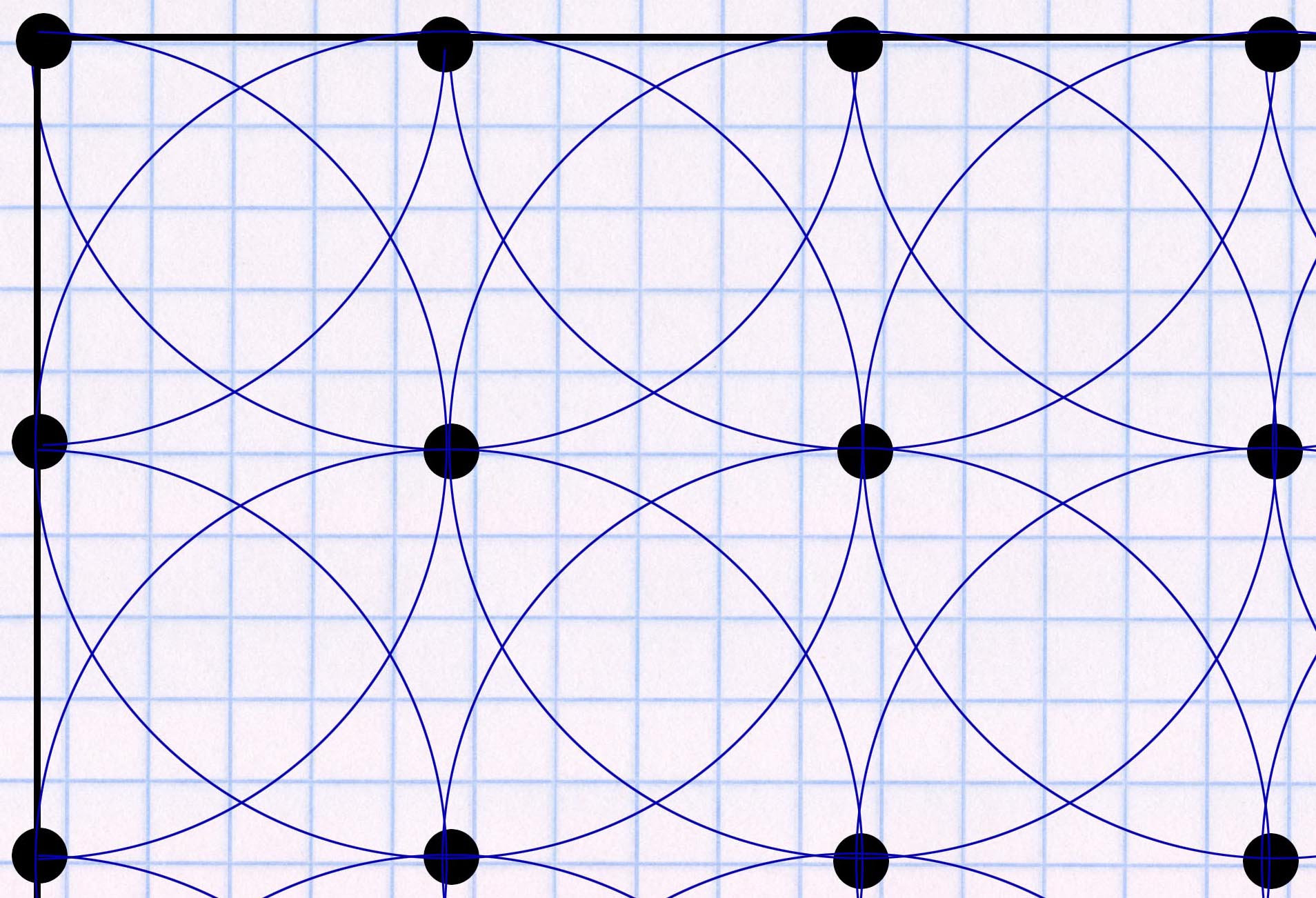
From these examples you can see very well that the geometric pattern created by the throwing circles is repeated continuously, i.e. all areas of the irrigation area are watered equally. This described way of placing the sprinklers is called a “square pattern”, since 4 sprinklers placed on the plan result in a square shape and if you go through the system in this way, many squares can be seen on the plan at the end of the planning. In practical terms, it is the simplest system. In the following blog post you will get more information about the square pattern and how to use it in practice.
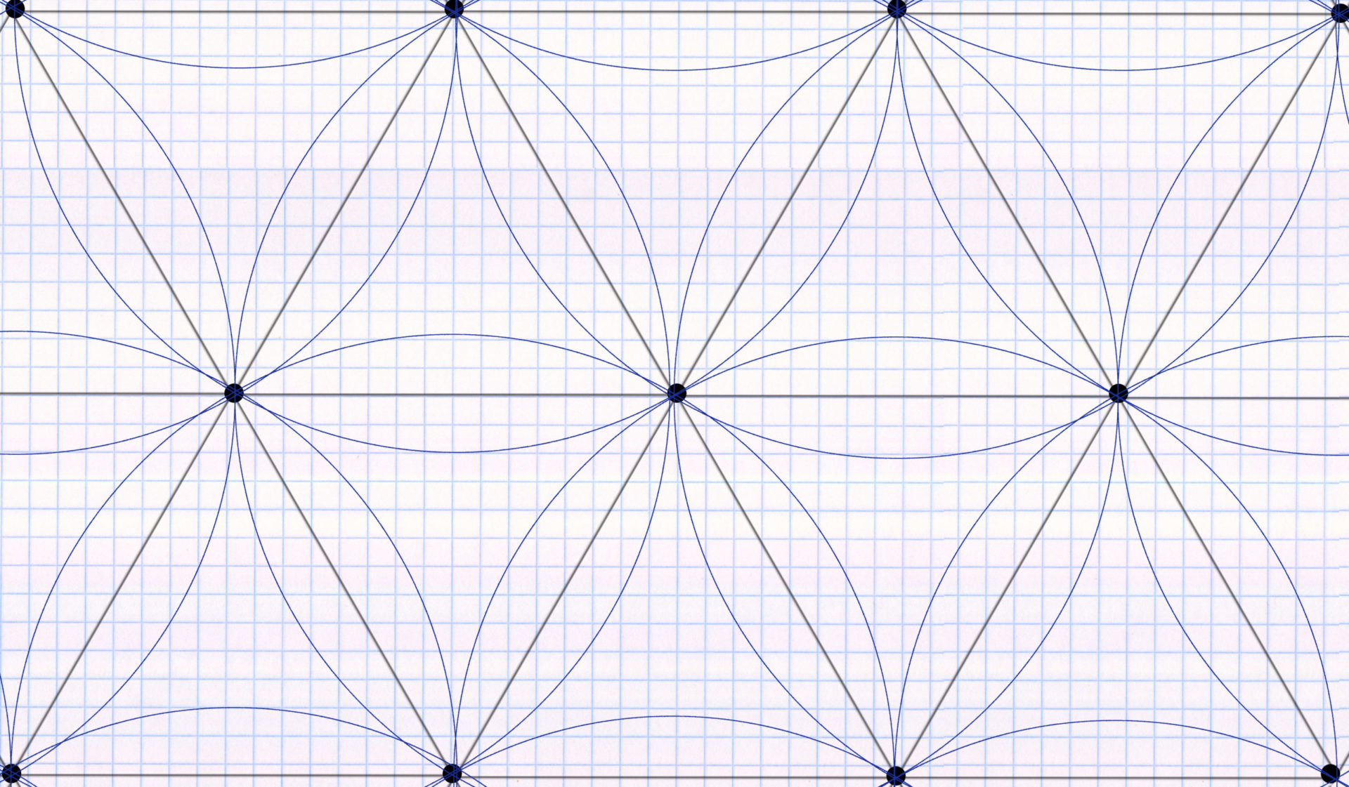
The alternative to this is the “triangular pattern”. In this, not 4, but 3 sprinklers form a formation and these together do not form a square but a triangle. In the following blog post you will learn how the triangular pattern works in detail. Compared to the square pattern, the overlapping area is a little smaller and the water consumption is a little lower (in the square pattern, the sprinklers are placed on average at a distance of 50% of the sprinkler throw diameter from each other (i.e. exactly in the throw), in the triangular pattern at a distance of 60% of the sprinkler throw diameter).
When to use what? I would rather recommend the square pattern for ease of use, especially if the garden is made up of rectangular shapes. In this case, it is easier to use the square pattern at the edges of the rectangles. If the shape is not rectangular, then it might be worth using the triangular pattern. This is especially true if the garden or a part of it has a round shape.
Irrigation manufacturers also refer to these two systems, i.e. the square pattern or the triangular pattern, in their documents when they state the amount of precipitation for a sprinkler. This is always given for the square pattern (usually marked with a square) and the triangular pattern (usually marked with a triangle). It then looks like this, for example:
Hunter PGJ
0.57 inches per hour, as given here in the example for the square pattern, corresponds to 0.37 gallons of water per square foot. The lawn contains this amount of water per hour if it is watered with this sprinkler, with the specified nozzle and the specified water pressure, according to the rules of the square pattern. If instead it is irrigated according to the rules of the triangular pattern, then every square foot receives 0.42 gallons of water. The overlap resulting from the selected formation is included in these numbers. It is therefore taken into account that the area to be irrigated receives water not just from one but from several sprinklers. A more detailed explanation of this principle can be found in the following blog post.
Tricky geometric shapes
Below is information on the correct watering of two somewhat more difficult special cases:
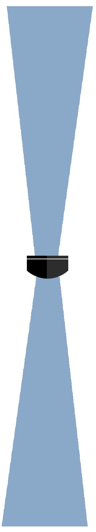
Narrow stripe
This is where the usual circular sprinklers reach their limits. The sprinkler suppliers have their own strip nozzles in their range for this application, which have an almost rectangular, long and narrow spray pattern. For example, there are nozzles with a spray pattern of about 15 x 5 feet. A strip is always irrigated by 3 strip nozzle sprinklers together: All three are placed on the same side, one in the middle and the other two at the corners. When buying you have to be careful that there are suitable strip nozzles for the left corner, for the right corner and for the middle. A strip irrigation then looks like this, for example:
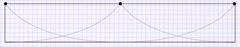
To ensure that all edges are perfectly watered, you should – if the circumstances allow it – plan a small cover, i.e. sprinkle a little over the edge.
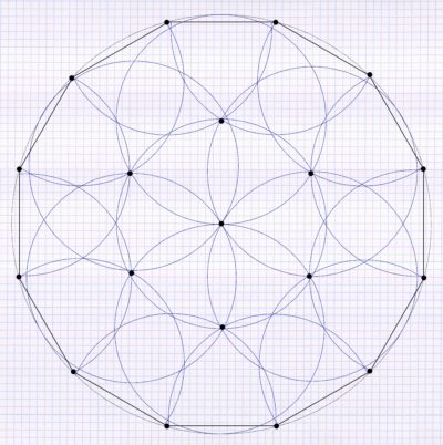
Circle
The best way to water a circle is to start at the edges of the circle and set the sprinklers in a triangular pattern. Exactly how this works is explained step by step in the blog post on watering circular areas. For example, the result looks like this:
7. Selection of sprinklers
Before the sprinklers can be drawn on the plan, you have to think about which sprinkler model or models you want to use. Because that significantly influences the framework in which you can move and determines the range with which you place your sprinklers in the square or triangular pattern described above. In the planning tips, it was already mentioned that sprinklers can irrigate a maximum of 65 feet. However, this is the absolute maximum limit, the actual throw distance will usually be significantly lower due to the available pressure.
Let’s say, based on the water flow measurement you made earlier, you want to operate your pipeline with 40 psi of water pressure applied to the sprinkler. Now you first have to decide on a specific sprinkler and then determine the range of throw of this sprinkler at a pressure of 40 psi. Manufacturers provide this sprinkler performance data in their documentation. In the following blog post I have compiled the performance data of the most important sprinkler models.
If you want to do your own research, you can also find this information in the manuals/product catalogs of the irrigation companies:
The radius information for your sprinkler model now looks like this, for example:
| Pressure in psi | Throw in feet (= radius) |
|---|---|
| 30 | 17 |
| 40 | 19 |
| 50 | 21 |
In the example table, the radius at 40 psi is 19 feet. Experience has shown that the manufacturer’s specifications are calculated optimistically, i.e. only under laboratory conditions, but can hardly be achieved in practice. You should therefore plan carefully with about 10% less (= in this case about 2 feet less). If the radius of the sprinkler is too large in practice, you can easily shorten it using the adjusting screw on the sprinkler, the reverse is not possible. Thus, the largest possible circle diameter that you can draw on the plan would be 17 feet in our example.
Narrow stripes
In the example garden, a narrow strip of lawn behind the house also needs to be watered. The use of sprinklers with special strip nozzles is recommended for this (see point 6 “Irrigation of tricky geometric shapes”). One sprinkler is needed for the middle, one for the left corner and one for the right corner. In the example, we use a strip sprinkler with a spray pattern of 30 x 5 feet for the center and corner strip sprinklers with a spray pattern of 15 x 5 feet for the left and right corner. The spray pattern is achieved from a water pressure of 30 psi and does not increase further at higher pressures. As previously written, the specified rectangular spray pattern is not quite achieved in practice. If the local conditions permit, a small cover should be included in the planning so that all peripheral areas are also watered. Here, too, the performance specifications of the manufacturer should be reduced by 10% to be on the safe side.
8. Place sprinklers and sprayers on the plan and mark the area they will water
Now the time has come and you can place the appropriate sprinklers, sprayers and micro-drip elements on the plan made in point 2. For this purpose, it is important to consider at which position the installation should take place, in order to irrigate which part of the garden. These irrigation areas are drawn in circles with the help of a compass or – if only part of the circle is watered – in the form of circle segments.
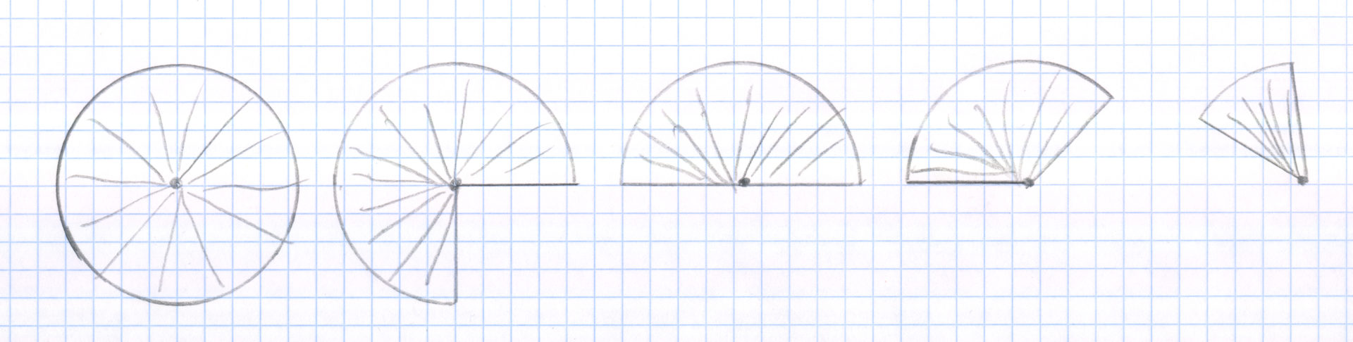
Examples of plotted irrigation areas in different circle segment sizes on graph paper. When drawing in, the compass is set true to scale. So, for example, if a box on the plan is to be 5 feet long and the circle radius (throw) is 25 feet, then the compass is set to a width of 5 boxes.
At this point, you should already know what model of sprinkler you want to use and what throw range it will have at the intended water pressure. You should also have considered whether you should place the sprinklers in a square formation or in a triangle formation.
In our example, we chose sprinklers with a range of 26 feet and a water pressure of 40 psi. And the sprinklers are set in square formation. Based on the application example given above with the large continuous lawn area, a specific application example would look like the one shown below:

A total of 12 sprinklers were planned here. At first glance, this may seem like an unnecessary amount, but it is necessary to water the lawn in a correct square formation. The tree that stands in the way is therefore not particularly important, because it rains towards the tree from several sides and thus all areas around the tree are hit.
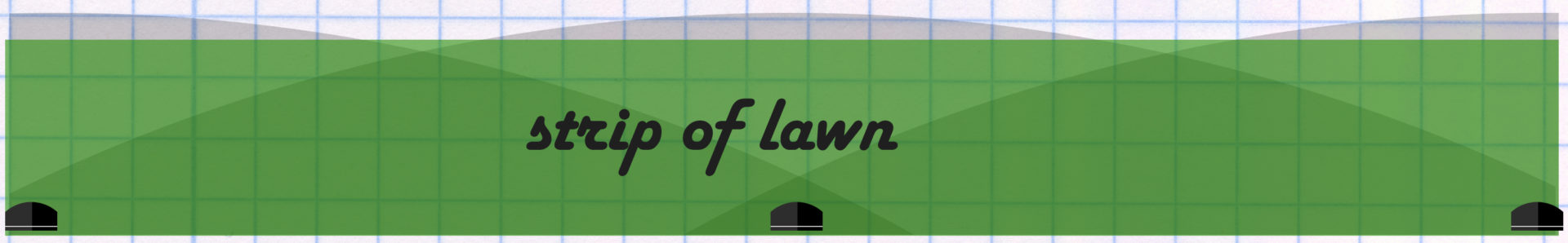
Narrow lawn strip
In addition, a narrow strip of lawn behind the house needs to be watered. In any case, this should be planned separately, as there is probably a significantly different water requirement here than for the large lawn in front of the house. Due to the strip shape, which is difficult to irrigate using square or triangular formations, strip nozzles are used here. A concrete application example would look like this. Here it is also planned that something is irrigated beyond the area to be irrigated, since in practice strip nozzles do not irrigate perfectly rectangularly and otherwise small areas would remain dry:
Tip: If you already know exactly which sprinkler model you are going to use at this point, then write the sprinkler name together with any model variant right away on the plan for each sprinkler! This will help you to correctly determine the number of sprinklers later when purchasing the sprinklers.
9. Drawing in the drip irrigation (drip hoses, micro-sprayers)
Now it’s time to plan the watering of non-lawn plants, i.e. hedges, bushes, vegetable beds or plants in flower pots or flower boxes. Here, water pressure and the amount of water available play a far less important role than before, which makes planning much easier. Subsequent adaptation/expansion is also possible with comparatively little effort.
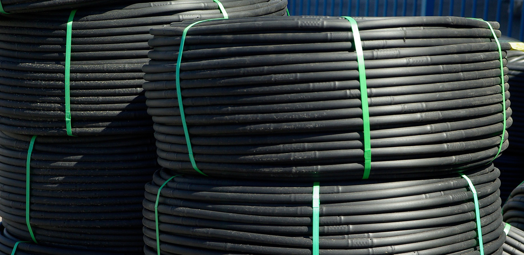
Drip irrigation
Drip hoses are ideal for watering hedges or connected rows of bushes. These are hoses or, in practice, mostly pipes that are prepared in such a way that water drips out at short intervals. The drip hoses are laid – usually above ground – along the area to be irrigated (but there are also underground systems). A light covering with mulch to make them disappear visually is not a problem.
In our example, the thuja hedge is supplied with a drip line. These are plants with a slightly higher water requirement.
Note: In the case of a hedge, you can roughly calculate with a water requirement per plant of 2 gallons per week per meter of height of the plant. For example, for a 2 meter tall hedge this would be 4 gallons/week per plant.
I would recommend either 0.5 or 1 gallon per hour drippers here. This means that a dripper will dispense 0.5 or 1 gallon of water per hour. A smaller capacity has the advantage that the water enters the soil very slowly, further ensuring that the plant has enough time to absorb the water. This means that as little water as possible is wasted. Allow 12 inches to 16 inches spacing between drippers. 12 inches for more sandy soils and 16 inches for clay soils where the water seeps into the earth less quickly and thus spreads out more widely. In our example 1 dripper is set per inch of drip line. Therefore, using 0.5 gallon drippers, 0.5 gallons of water will be dispensed in one hour for every inch of drip line. With an assumed water requirement of 4 gallons per thuja and an average of 2 thujas per 3 inches (i.e. a water requirement of 8 gallons per 3 inches), the sector would have to be watered for approx. 5 hours and 30 minutes. Using 1 gallon drippers would take half as long.
Isn’t it possible to make such a drip tube yourself? By simply poking holes in a pipe at foot intervals? In principle yes, in practice it’s just not a good idea! The water will spurt out of the holes in a very strong and misshapen manner. And there is no uniformity across the individual holes: more water comes out of one hole, less from the other. This means that even watering is not possible and water is wasted. Since the drippers are not too expensive either, you can safely save yourself the money.
Is the amount of water sufficient?
Having the necessary water pressure is not a problem with drip irrigation – on the contrary, the water pressure usually has to be lowered here. With a pressure regulator, it is reduced to the level of mostly 22 to 26 psi that is suitable for drip irrigation. However, a limiting factor in drip irrigation is the amount of water. The drip line can only be as long and supply as many drippers as the water volume allows. If you exceed this limit, the drippers will no longer work correctly and will not release the desired amount of water.
The outermost framework in which one moves is of course also with drip irrigation the amount of water measured at the water extraction point. In our example, that was 600 gallons. As we already know, however, this cannot be used in full, since there are pressure losses on the way from the withdrawal point to the point at which the water is dispensed. And a certain pressure on the side walls of the drip tubes is also necessary for the drippers to work. Both slow down the flow of water. With drip irrigation, however, there is a much larger, limiting factor: the pipeline of micro-irrigation is not formed with 3/4 but with 1/2 inch pipes. These form quite a bottleneck! A 1/2 inch pipe will only pass about 150 to 210 gallons of water per hour at a given drip irrigation pressure of about 22 to 26 psi and assuming a pipe length of 80 to 100 feet. So that 150 to 210 gallons is the frame we need to stay within. If the need is higher, the drip hose system must be divided into several sectors. If a length of pipe longer than 100 feet is required, then there are two ways to help:
- The pressure regulator is not connected to the beginning of the drip tube, but to the middle. Here the upper limit is then a maximum pipe length of about 200 feet.
- Or the main line is routed not to one, but to several pressure regulators, to which the drip line is then connected. In our example, with 600 gallons of water available at the water source, it would be possible to feed two strings of drip tubing at the same time.
In our example, the hedge has a total length of 140 feet. Since a 0.5 gallon dripper is set per foot, the total water requirement is 70 gallons per hour (=140*0.5). That is well within the 150 to 210 gallon range and can thus be operated in one sector. Even with the alternative use of 1 gallon drippers, it would still work out well with 140 gallons of consumption. Due to the length of 140 feet, the pipeline is connected to the main pipe at its center as described in point 1).
For the sake of simplicity, it makes sense in our example to also supply the flower box adjacent to the hedge and the two flower pots that are very close by in the same sector. Strictly according to the principle, a separate drip line sector would have to be provided for this due to the different water requirements. But that’s hardly worth it here, so it makes sense to simply compensate for the different water requirements by using other drippers.
Note: With such a procedure, i.e. the use of drippers with different capacities, different water requirements within a sector can be compensated for in micro-irrigation. This would also be necessary, for example, if 50 different flower pots with different plants and different water requirements are hanging on a sector. You then lead a line to each flower pot and provide it with the appropriate drippers. However, this principle does not work if the plants also require a different watering frequency, e.g. one plant has to be watered weekly and the other every 2 days.
Since the flower pots are quite far away from the hedge and you would have to plan the drip line with an unnecessarily long length, it makes sense to split the main line as described in point 2) and the flower pots with their own pressure regulator and their own connected to it supply drip line.
The drip hose to be laid can be recorded on the plan as follows (drip hose in red):
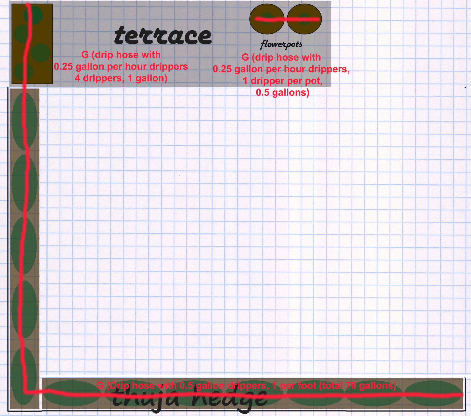
The main challenge here is to lay the drip hose as invisibly as possible and as unobtrusively as possible. This is not a problem under the thuja hedge, but with individual flower pots and boxes, care should be taken to plan as cleverly as possible. More on this in the following points and in the Installation section.
Note: Always route the large main pipeline pipe as far as possible and, conversely, always start the 1/2 inch drip pipe as late as possible! This results in the lowest possible loss of pressure and water volume. For example, a very bad idea would be to bridge the water line 70 feet from the hedge with a 1/2 inch pipe. Instead, you run the main pipe up to the hedge (or in the case of longer drip pipes up to the middle of the hedge), connect the pressure regulator there and only continue here with the small 1/2 inch drip pipes. The same applies if you use the even smaller distribution pipes, with which you can lead the water unobtrusively to individual flower pots or make small branches: Always branch off the 1/2 inch pipe as late as possible!
Micro spray irrigation
Micro-spray irrigation uses the same micro-irrigation pipeline as drip irrigation. So a 1/2 inch pipe with the pressure reducer connected in front of it. The only difference is that the water is not dispensed via drippers, but via micro-sprayers that release the water in a fine mist. The sprayers release significantly more water in the same amount of time than drippers do, so they should not be operated in a common sector, as the running times do not match.
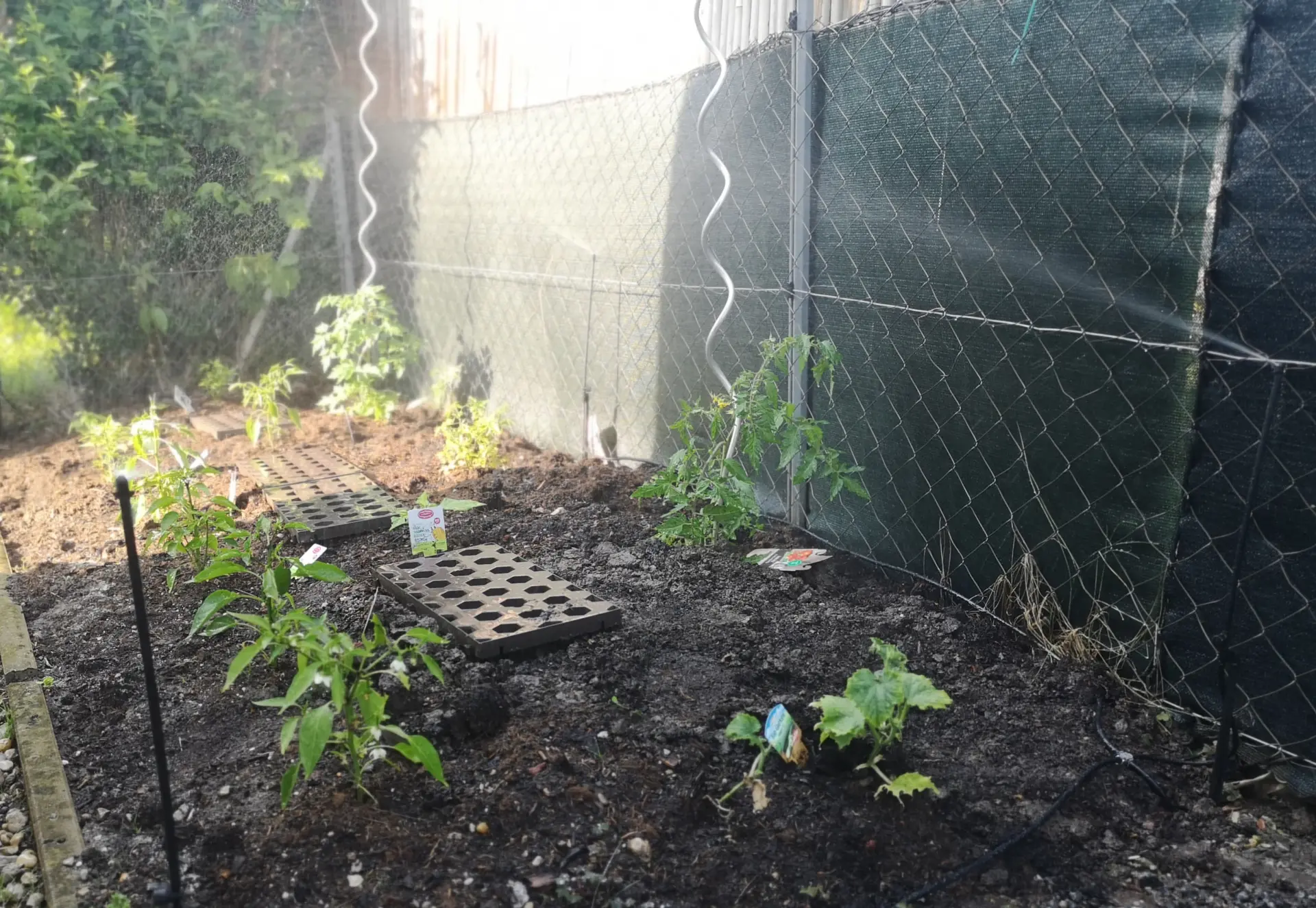
So when do you use sprayers instead of drip irrigation? These are ideal for areas that are regularly walked on or worked on, such as a vegetable patch. Of course, you could also lay a drip hose in tracks through the bed. But that would have the disadvantage that you would be disturbed by the hose lying around when working in the bed, for example when weeding. Instead, micro-sprayers are a good idea, which can be placed at the corners of the bed so that they are not very disruptive and can thus be used to water the entire bed. Why not use ordinary sprinklers or sprayers? Micro sprayers irrigate much more gently and finely, ordinary sprinklers or sprayers would wash the soil out of the bed.
Depending on how high the plants to be watered are in the bed, the sprayers are placed on more or less high extensions. It is important that they tower over the plants so that the spray mist is not disturbed by individual plants.
Basically, a distinction is made between the micro sprayers according to the following properties:
- Size of the irrigated circle section (full circle, semicircle, quadrant)
- Shape of the spray pattern (discharge of the water as a continuous water screen or in individual jets or circular or strip-shaped)
- Individual setting option (possibility to direct water to individual plants or not)
In our example, a vegetable patch needs to be watered. Since it has an elongated shape, micro strip nozzles are ideal here. These water a long and at the same time narrow area. The spray pattern of an end strip nozzle looks something like this:

I place these at the top and bottom of the vegetable patch:
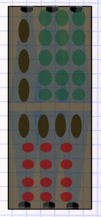
Depending on the type of plants to be watered, this may already be sufficient. Due to the cone-shaped spray pattern, however, the area around the sprayers receives comparatively less water and some areas remain dry. A more even irrigation can be achieved with an additional row of sprayers in the middle of the vegetable patch. In this case, you don’t use end stripe nozzles, but stripe nozzles that throw a stripe in both directions:
It finally looks like this:
Because some plants grow tall, it makes sense to plan for a height extension of at least 1 1/2 feet or more for the micro sprayers.
Further information on the subject of micro-irrigation
In the following blog post, I present the individual components of micro-irrigation in detail:
10. Optional: Draw in the planned water extraction points
If additional water extraction points (irrigation hydrant valves) or a handle pump are planned as part of the irrigation, then these should now be added to the plan, as they also have an influence on the planning and must be operated in an independent sector.
11. Plan sectors
Now it is necessary to consider how many and which sectors the irrigation is divided into. So which sprinklers, sprayers and other elements are operated together on a water line.
For your information: Even if several sectors are required, as is usually the case with irrigation projects, this does not mean a problem or a high additional effort. A water source is still sufficient. In this case, this does not supply all the plants to be watered with water at the same time, but the divided sectors are run through one after the other, i.e. the watering of sector A is started, then it is the turn of sector B, etc. etc.
Is a division into sectors necessary at all?
In principle, it is also possible to operate the entire irrigation in just one sector, for example if you only supply water to a very small area. In order to be able to dispense with the division into several sectors, the following points must apply:
- Only sprinklers or only sprayers are planned for irrigation.
Mixing sprinklers and sprayers in a common sector is not possible! - The plants and areas to be watered can be sensibly combined.
If only lawn is poured, this is not an issue. But if you also plan to water vegetable beds, potted plants, hedges, etc., then these have a completely different water requirement than the lawn. In a common sector, some plants would potentially receive far too much or, conversely, far too little water. This is even more true when plants have to be watered at different rates. Therefore, it definitely makes sense to operate very different plants in different sectors. This also keeps you flexible if, for example, the need for water increases or decreases in one area and you can then react without considering the other areas. - The amount of water is enough to water everything at once
Divide into sectors
How many sectors are necessary can now be determined by comparing the performance of the available water source with the water consumption (flow rate) of the planned sprinklers (at the planned water pressure). You can find the water consumption per minute for the commonly used sprinklers in the following blog post. If you would like to research on your own, you will find some research sources under point 7).
Let’s start with the large lawn. For each individual sprinkler – in most models in combination with the nozzle used – it is precisely specified what water consumption it has in gallons per hour.
For each sprinkler you now write down – preferably right away on the plan – what water requirement it has. See sketch using a Hunter “MP Rotator 3000” sprinkler as an example:
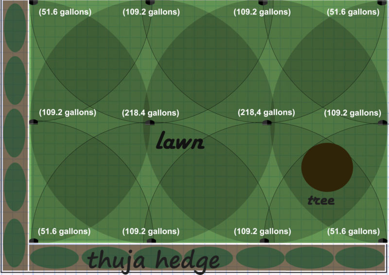
Now sum up these values. This represents the total water requirement of your sprinklers per hour. In our case, we use the same sprinkler on the entire lawn. If you plan to include both sprinklers and sprayers, then do not add up together, but add up for both groups. The same applies if you have planned sprinklers with different purposes and, as a result, different durations. A separate sum must be calculated for each group of sprinklers with different purposes.
Now compare this sum or sums with the capacity of your water source. This does not mean the amount of water that was measured in the bucket test, but the amount of water that actually flows through the pipeline at the water pressure that is supposed to prevail in the pipeline! So the water flow determined in point 4.
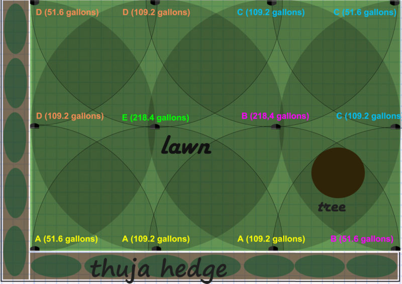
In our example, with a pipeline pressure of 40 psi, the available water rate is 280 gallons per hour. The 12 sprinklers have a total water requirement of 1,298.4 gallons per hour (2 x 218.4 gallons, 6 x 109.2 gallons, 4 x 51.6 gallons). Thus, the watering for the large, connected lawn area must be divided into at least 5 sectors (calculation: 1,298.4/280 = 4.64, -> rounded up = 5). You can find out whether 5 sectors are actually sufficient in practice, or whether a sixth sector is perhaps also necessary, by trying out the possible combinations. It makes sense to also pay attention to the spatial proximity, i.e. sprinklers that are as close together as possible are combined in one sector. In our example, the sprinklers could be divided into the following 5 sectors (sectors are named A to E and marked with different colors):
Check of calculation:
Sector A: 51.6 gallons + 109.2 gallons + 109.2 gallons = 270 gallons
Sector B: 51.6 gallons + 218.4 gallons = 270 gallons
Sector C: 109.2 gallons + 109.2 gallons + 51.6 gallons = 270 gallons
Sector D: 109.2 gallons + 109.2 gallons + 51.6 gallons = 270 gallons
Sector E: 218.4 gallons
The hourly water requirement in all five sectors is below the available water volume of 280 gallons. Thus, all 5 sectors can be realized as planned.
Strip of lawn behind the house
Now the procedure for the lawn strip behind the house is repeated.
The three sprinklers planned here have a total water requirement of 52.8 gallons/hour at a water pressure of 40 psi (= optimal pressure recommended by the manufacturer for these strip nozzles). This is well below the available amount of water. The lawn strip can therefore easily be realized as a separate sector.
Micro-irrigation thuja hedge
So to the parts that are supplied with micro irrigation. First to the thuja hedge including the neighboring flower box and the two flower pots. A drip hose is planned for these.
The hedge requires 70 gallons per hour. The flower box requires 1 gallon and the 2 flower pots 0.5 gallons. That makes a total of 71.5 gallons per hour. The limits for micro-irrigation have already been specified in point 9). For a 1/2 inch pipe with a length of 80 to 100 feet you can expect a water volume of about 150 to 210 gallons/hour. The 71.5 gallons are therefore far below the available amount of water. The drip hose can therefore be operated as a separate sector without any problems.
Note: With the amount of water that is available in usual, average irrigation projects, you could usually even operate two drip hoses with 150 to 210 gallons/hour each in one sector at the same time. If more water is required per hour or if the maximum possible pipe length (approx. 200 feet if the pipe is connected to the pipeline in the middle) is exceeded, a division into sectors would also be necessary here. The same applies if plants cannot be irrigated in a common sector because the water requirements and, above all, the watering frequency are different. In any case, drip hoses and micro sprayers should be operated in separate sectors due to the very different water delivery quantities.
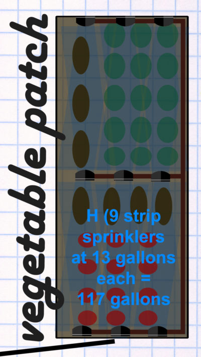
Micro irrigation vegetable patch
The strip nozzles and end strip nozzles used in the example each have a consumption of approx. 13 gallons/hour. All nine together so 117 gallons/hour, well below the available amount of water. The bed can therefore be operated as a common sector without any problems.
12. Draw in pipeline
First, the water connection point is drawn, preferably symbolized with a water tap.
In our example, that would be an outside faucet on one side of the house:
Ideally, the sprinklers in the sprinkler sectors are not connected in series, but either in a circle or in parallel to the irrigation pipeline. This has the advantage that the pressure is distributed as evenly as possible in the pipeline, i.e. the first sprinkler does not get much more pressure than the last one in the row. You can find out how this works in the following blog post on the ideal integration of sprinklers into the pipeline.
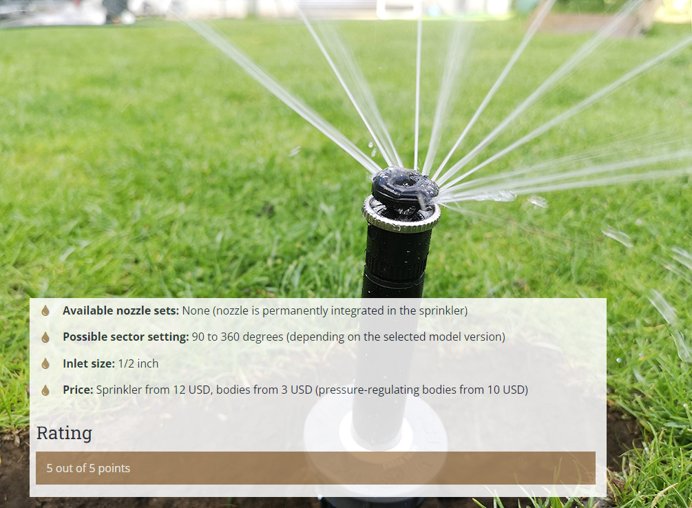
However, you do not need to plan in a way that is too cumbersome and material-intensive in order to achieve these ideal scenarios. Because even pressure distribution can nowadays also be easily achieved with pressure-regulating sprinklers or pressure-regulating bodies. These automatically reduce the pressure to a specified maximum so that the first sprinkler does not have more pressure than the last. Therefore, nowadays you can alternatively make the planning as simple and as material-saving (shorter pipeline routes) as possible and regulate the pressure directly on the sprinkler.
The pipeline is now drawn from the water connection point. Each sector must be connected to the water connection point with its own pipeline. In our case, with 8 sectors (A to H), this also means 8 pipelines that lead to the sectors.
First you start with the first sector and draw the pipeline from the water connection to the first sprinkler and then continue this to the other sprinklers. In our example I start with sector C:
As you can see, you have to branch off in some places. The pipeline (drawn with black lines) first runs along the house wall and then splits at right angles at the beginning of the lawn into two strands running to the left and right. For this splitting you need a connector, a so-called T-piece. On the left side, the pipeline then becomes sharp, guided around the bend at a right angle. You need an L-piece connector for this.
Next, the pipeline of sector B is drawn. Sharp corners slow down the water flow and mean pressure loss. Therefore, in places where it is easy, instead of planning 90-degree corners, you should rather lead the pipeline as gently as possible around the curve, i.e. plan a long curve. Sector B contains two examples of this. Deliberately keep a little distance from trees, as strong roots in the immediate vicinity of the trunk can make the excavation work much more difficult!
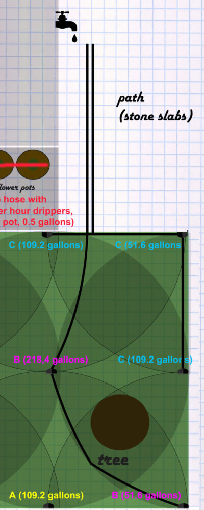
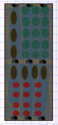
The other sectors are now being connected step by step in the same way. At the drip hose sector G, the pipeline is routed to the drip hose. Since the drip hose is quite long in our case, the connection should not be at one end of the drip hose, but rather in the middle of the drip hose. At sector H (vegetable patch with micro-irrigation spray nozzles), the pipeline is routed to the vegetable patch. From there the pipeline goes into the micro-irrigation system, the individual sprayers are then supplied with a smaller pipeline from the micro-drip system. The plan now looks like this:
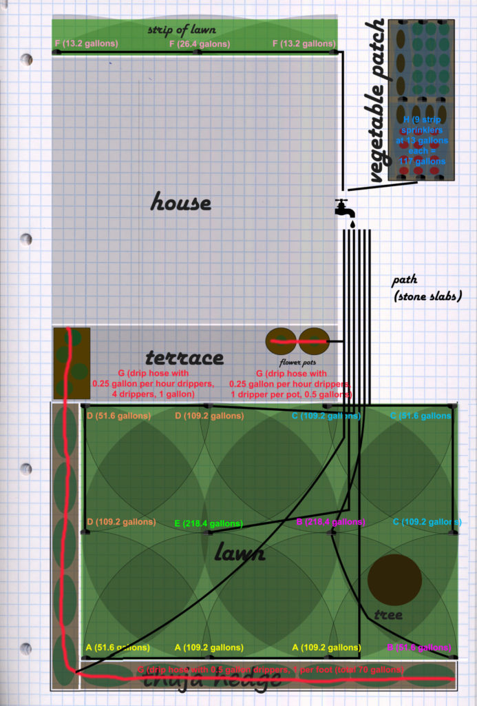
Finally, the micro-drip pipeline is drawn in the vegetable patch (brown lines):
Drainage
If you would like to equip your irrigation system with a drainage system to protect against frost, then also mark the point where the drainage (drain valve or ball valve) is to be installed in the plan for the pipelines. This must be the lowest point in the irrigation. If you are still undecided on this, then read my blog post on drainage first.
What are the next steps?
Think about irrigation control
As a final planning point, the future planned control of the irrigation must now be considered. Is this simply attached directly to the faucet or pump? Do you work with a manual distributor or with switching via solenoid valves? Is an irrigation computer used, and if so, which one? In principle, all of this can still be decided when you have already installed the irrigation system, but you should at least think it through to the point that you don’t have to change anything significant in the installation that has been carried out.
In the Controlling menu item, you can find out what options you have for controlling and automating your irrigation system and how they are implemented.
Make a parts list for purchase
You can use the plan you have created to create a parts list for the required sprinklers, pipes, connectors, micro-irrigation components, etc. This then forms the basis for purchasing the required products. Concrete purchase recommendations can be found in the Purchasing menu item.
Install the irrigation
Once you’ve got everything you need, you can proceed to assembling the sprinkler system. It is best, however, to take a quick look at this menu item in advance in order to clarify whether there are any tools or aids that you should obtain in advance.

Online cost calculator – How much would an irrigation system for your garden cost?
With the Irrigation Guide online irrigation calculator, you can calculate the expected costs for installing an irrigation system with minimal effort. All you need is the approximate size of the lawn and garden bed area [...]
Introducing Orbit Online Irrigation Planner
In this blog I have already presented two free online tools for planning garden irrigation: the DVS irrigation planner and the myGarden planner from Gardena. Unfortunately, the former is currently only offered in German language [...]
Determine the water pressure with a manometer – this is how it works
In order to ensure that the garden can be irrigated with the available water source, not only the amount of water that can be drawn from the water source per hour is relevant, one [...]

Overview of the most important suppliers on the irrigation market (Hunter, Rain Bird, Toro, Gardena/Orbit)
As a consumer, you are spoiled for choice between a number of irrigation system suppliers. This blog post answers the most important players in the irrigation market, introduces the companies and gives an overview [...]
Determine the water flow rate at a specific water pressure
The water flow in a pipeline decreases in the opposite direction to the water pressure exerted on the pipeline. A water pressure and flow test gauge can be used to determine how large the [...]
Place the sprinkler correctly: Square pattern
The correct placement of the sprinklers on the area to be irrigated is one of the most important points when planning an irrigation system. Firstly, this is crucial for watering the garden as evenly [...]
Place the sprinkler correctly: Triangular pattern
The correct positioning of the sprinklers on the area to be irrigated is one of the most important points when implementing automatic irrigation. A distinction is made between two different principles, the square pattern and [...]
Irrigation of a circular area
A particularly tricky special case is the watering of a circular area. For example, since a circle tapers inward, using the square pattern here would work poorly. The triangular pattern is the suitable alternative for [...]
How do you water a bed?
In this article, I will explain the basic options you have for watering a vegetable bed with an automated irrigation solution and then show you how to install such a bed irrigation system in just [...]
Planning the pipeline: This is how the sprinklers are ideally connected to each other (parallel or in a circle)
In order to achieve the most even pressure distribution possible, the sprinklers are ideally not simply connected to the pipeline one after the other, but in systems that ensure the most even pressure distribution possible. [...]
Overview of the most important sprinklers including performance data
In order to choose the right sprinkler, knowledge of the properties and performance data of the sprinklers available on the market is necessary. This can be found mostly on the manufacturer's websites or sometimes [...]
Overview of the spray nozzles available on the market
This blog post gives an overview of the sprinkler nozzels available on the market, also known as spray nozzles or sprayers. Sprayers release the water like a shower head in a torrent in all [...]
Overview of spray bodies available on the market
A distinction is made between two parts in spray sprinklers: the nozzle and the associated body. Nozzle and body can be combined as desired and are also sold separately in stores. The body is [...]
How a water socket works and how it can be used
The term water socket is a word coined by the irrgiation company Gardena. Other manufacturers sell similar products under the names "water hydrant", "hydrant well", "quick coupling valve" or as a special kind of valve [...]
Tip: DVS Online Irrigation Planner
The range of online planning tools for planning your own garden irrigation is very small. For many years there was only one alternative for anyone who needed a free online tool to plan their [...]
How to calculate the precipitation rate?
Plants need a certain amount of water to thrive. For lawns, calculate about 1 inch of water per week that each patch of lawn needs to receive. In very hot periods even about 20 percent [...]