Assembling and setting up your irrigation system
The following describes the steps to install your irrigation, from digging, connecting the components, test run to fine-tuning the sprinklers and sprayers.
The basic prerequisite for starting the assembly and installation work is that you have completely completed the planning work. This means that you have created a plan of what the irrigation will look like and have thought about which components will be attached where. You should also have already thought about the specific products that you want to use, as these must meet the performance data assumed in the plan, such as throwing distance. Now you can start with the first implementation step …
… or test it beforehand?
This step is not required, but if you are still unsure …
- whether you have planned everything correctly?
- how do you cope with the products and how do you assemble them?
- whether the selected products are really the right ones?
- and whether they meet the planned performance data?
- want to test the whole thing again in detail before starting work?
… or if you just want to be on the safe side that you haven’t overlooked anything, you can do a dry test beforehand. There are also ready-made test sets that contain the essential components of lawn irrigation or drip irrigation. Or you can simply put together a set yourself with which you can test the essential parts of your irrigation. You can find out how this works in the blog post on building your own test environment.
Theoretically, it is also possible without any problems to assemble the entire irrigation above the ground in advance and let it run as a test. You then only have to make sure that the sprinklers are fixed in their position and that they are upright. And if you want to test the ranges, you should note that the sprinklers are higher than in the final version and therefore the throwing distances are greater.
But now to the first assembly step:
Digging trenches
Before you can start digging, you must first mark the canal to be dug and the components to be buried in the ground, such as sprinklers, water sockets, etc. To do this, you take the plan you have created and transfer it as precisely as possible to the lawn or earth’s surface. This can be done with cords that are laid along the canal and the sprinklers etc. can be marked with larger stones or sticks stuck in the ground, for example. If you want to be completely professional, or have it at home anyway, you can also use a marking spray. But that is not really necessary, better protect the environment and your wallet and simply use things that are available on site.
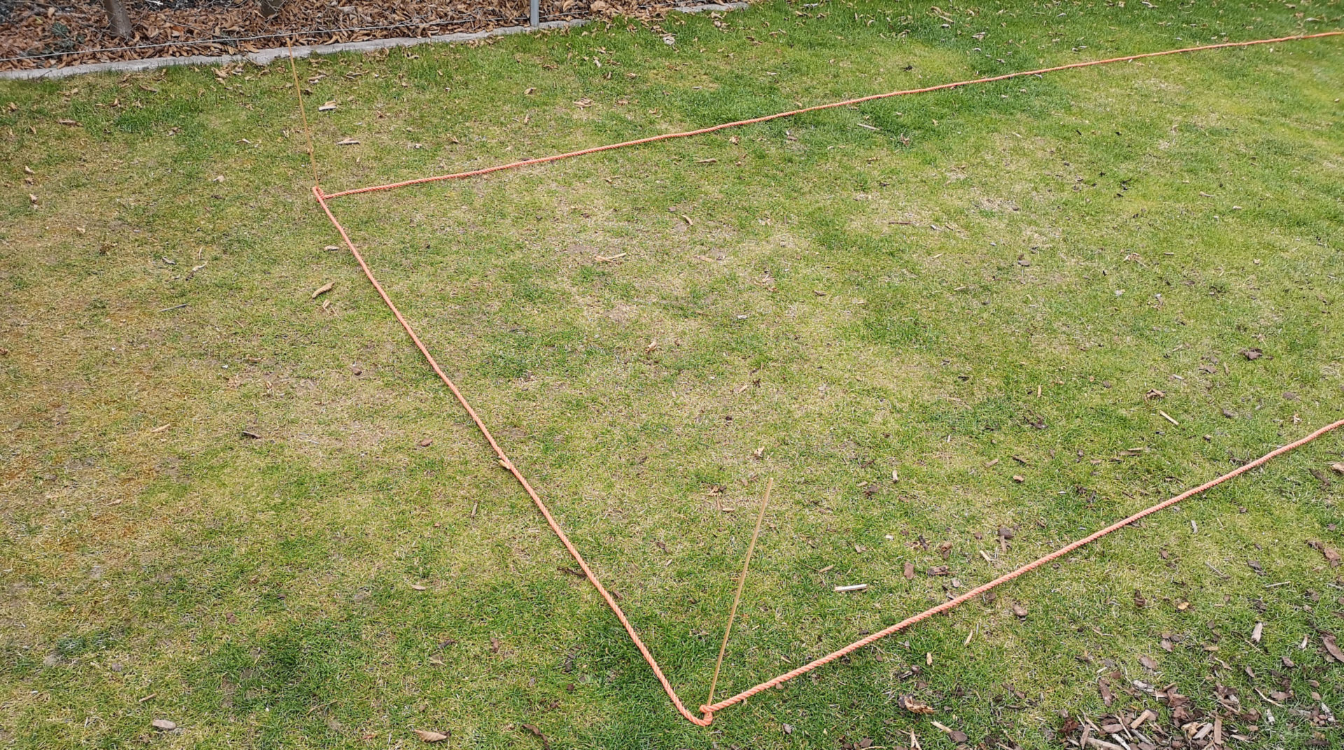
Example of a possible marking
Depth of the trench?
The first question that arises is how deep the trench should be. Answer: About 10 to 12 inches. This is about a spade length deep and thus a depth at which the pipes are quite well protected from accidental damage. The depth is too shallow to achieve absolute frost protection; this is achieved with other measures such as blowing out the pipes before winter or built-in drainage valves.
The next question is whether to dig manually with a shovel or to use electronic aids. For small and medium-sized gardens, most people will be able to do this by hand. In my experience, you can calculate with about 7 to 10 feet of dug canal for each digging person and hour. Depending on the length of the trench and the number of helping hands, this can usually be done in a few hours to a few days.
Trenchers
In larger gardens or if you are not quite as fit, it can be worthwhile to use a trencher. Trenchers are quite expensive to buy, in the price range of several thousand euros, which is why they are usually rented for one-time use. With sheer force, they pull a narrow, only a few inches wide swath into the ground. This also has the advantage that there is much less excavated material than with manual digging, so there is less earth in the way or has to be moved to the side.
The trenchers are used in such a way that they are brought to the starting point and there, by lowering a rotating piece of metal that looks like a rough chainsaw or a large-pronged circular saw, digs into the earth to the intended depth. Then the trench cutter is slowly pulled along the intended trench in reverse gear and in the process cuts a narrow channel into the earth. There are two types of trenchers: The classic trencher is a very heavy device that is permanently attached to a chassis and that is normally borrowed from a car trailer. The second type of trencher is a modern hand-held device and comparatively lightweight at less than 20 kilograms. It can therefore be used on the move and can be transported without any problems. It is either operated with 2 hands and pulled along the trench by hand, or it is placed on an additionally available, also very light and handy trolley attachment.
And let’s go …
The way you dig can easily be arranged in the way that is most comfortable and the fastest way to get ahead. It will also depend a lot on how solid the ground is. In the simplest case, the trench is simply shoveled shovel by shovel, in very hard soil, or if there are layers of rock in the ground, it may also be necessary to use the pick.
Tip: If it hasn’t rained in 2 weeks, or if the soil is inherently very hard, do yourself a favor and water it properly the day before the excavation work. This will soften the earth and make the excavation work much easier.
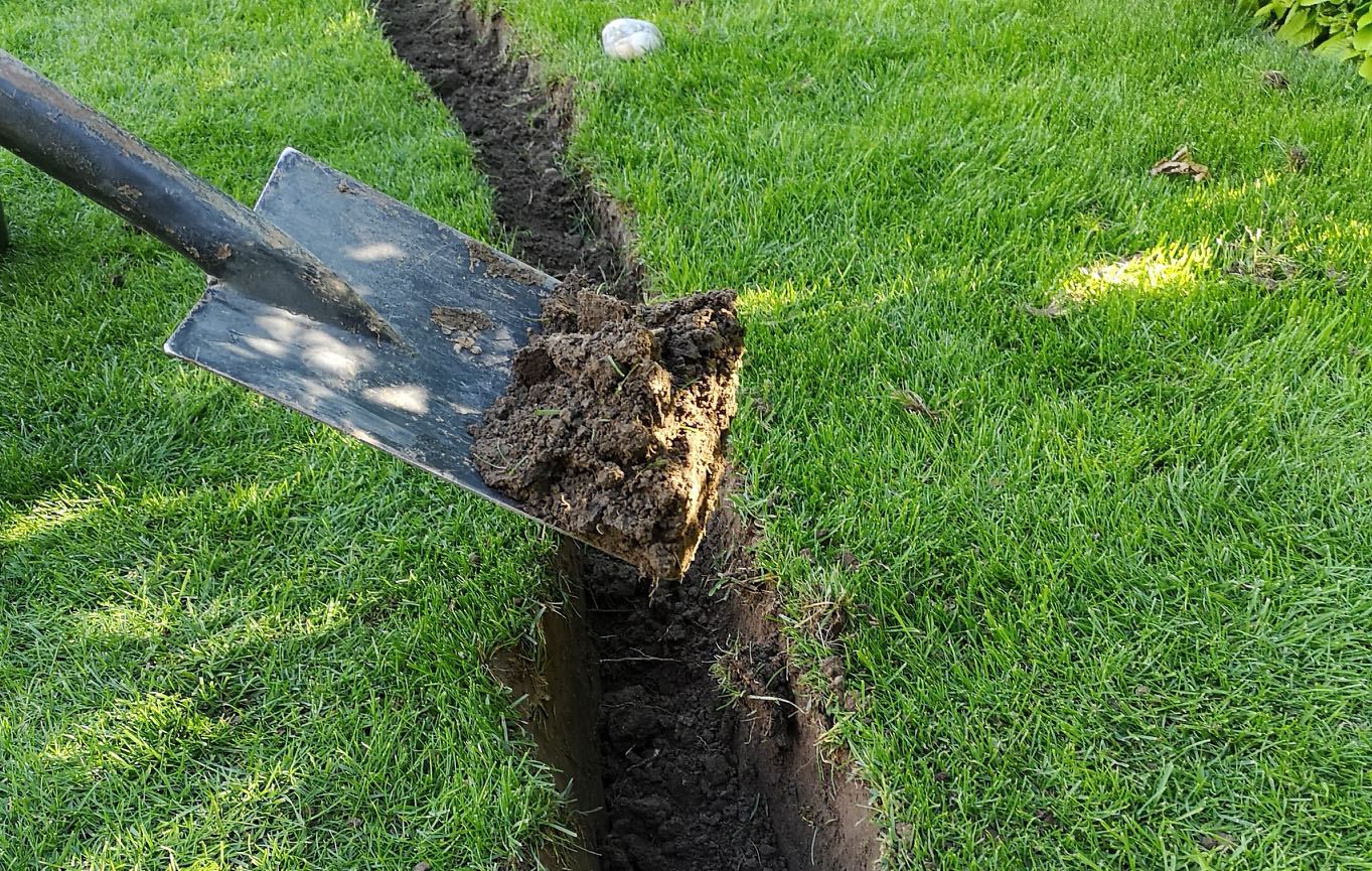
How beautiful the trenches are made does not really matter, as long as you reach the necessary depth. I deliberately do not go into the width, because only a very small width in the amount of the pipe diameter is necessary, which is exceeded with manual shoveling anyway. The challenge is rather not to get too wide so that the excavation does not become unnecessarily large. I myself like to work in such a way that I first pierce deeply with the spade along the canal to be shoveled and then repeat the whole thing about 4-6 inches apart. I then dig the pricked strip of lawn in a second step.
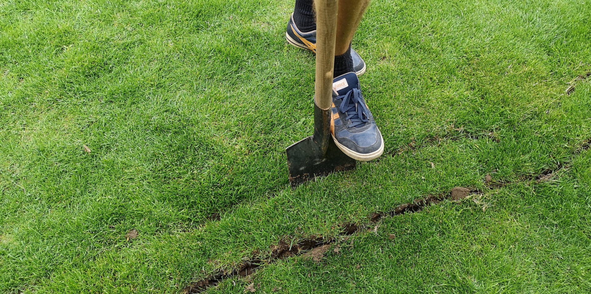
The course of the canal is marked by piercing with the spade
I then either push the excavated earth slightly to the side so that no earth falls back into the trench. Or, if the work is being carried out on an existing lawn, the earth is removed in a wheelbarrow and stored temporarily. Otherwise the lawn would be suffocated underground.
Preserve lawn sod
If you carry out the excavation work on an already existing, beautiful lawn, you will try to preserve the sod (= lawn including the roots). The sod can usually be removed relatively easily in the manner described above, i.e. by piercing left and right with the spade and then levering it out. It becomes even nicer if you cut the lawn cleanly with a soil or lawn knife.
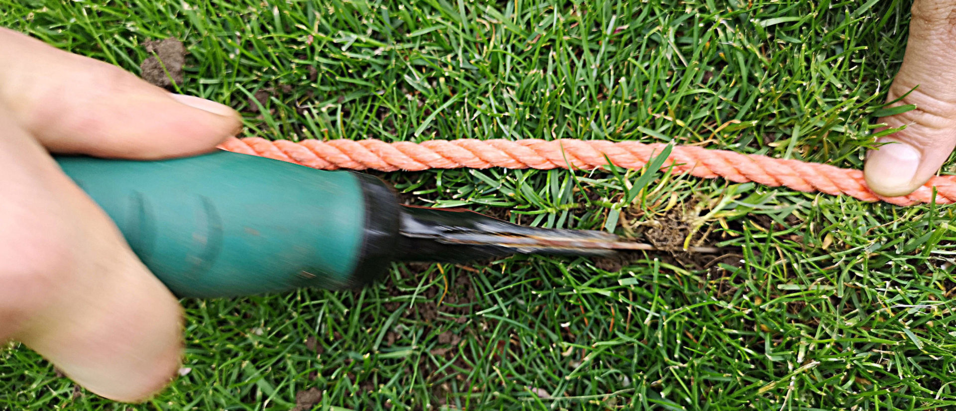
If you separate the sod with a soil / lawn knife, the cut is even more beautiful and finer
You start with the first piece of lawn strip and lift the sod out brick by brick.
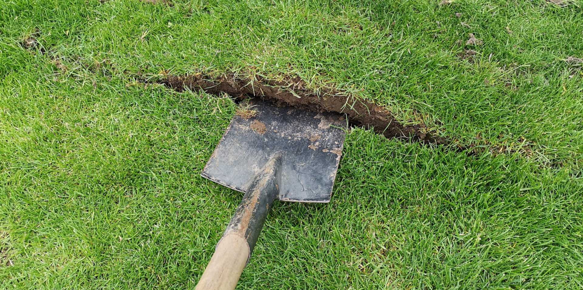
Pry it out with the spade
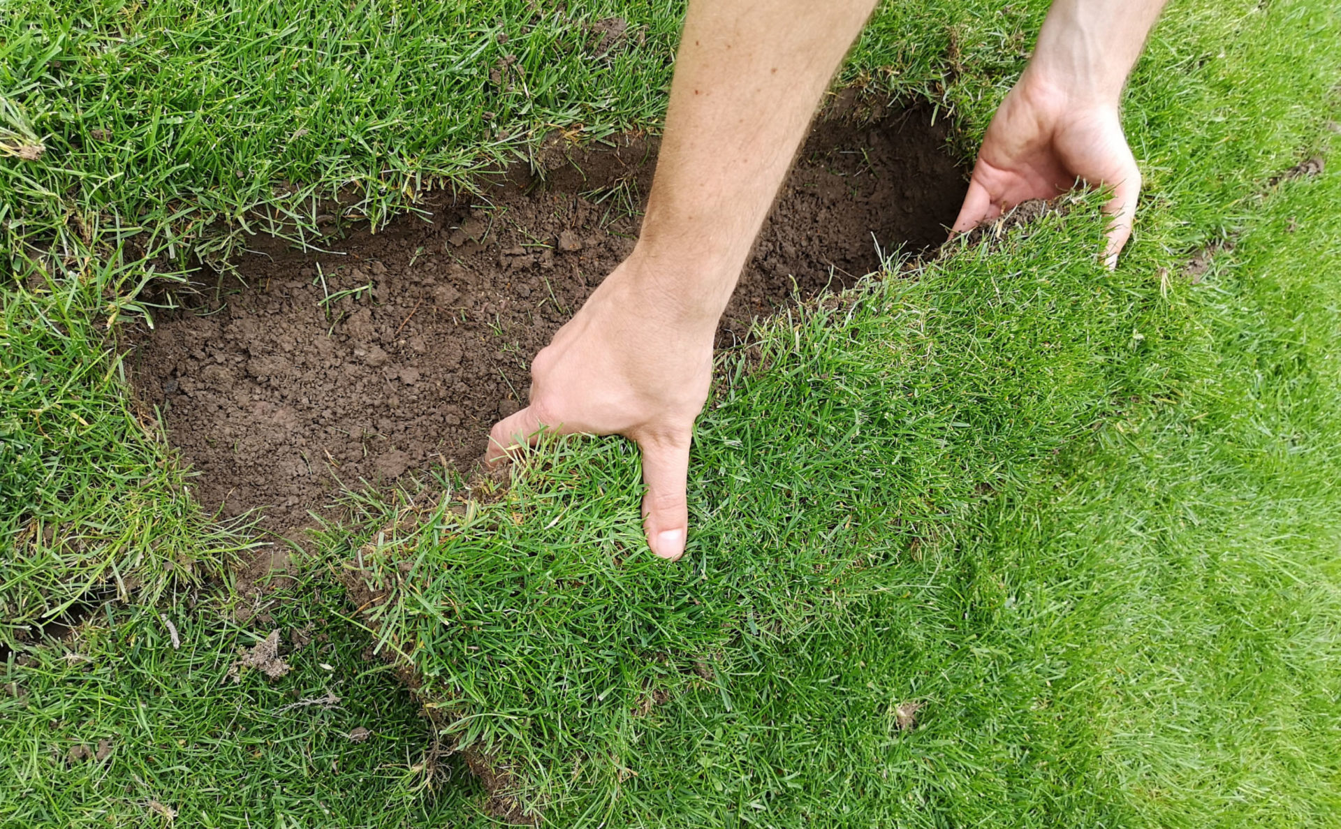
Then carefully lift out the piece of sod
This is then repeated in the same way for the entire canal section. The raised turf is best stored in a shady place.
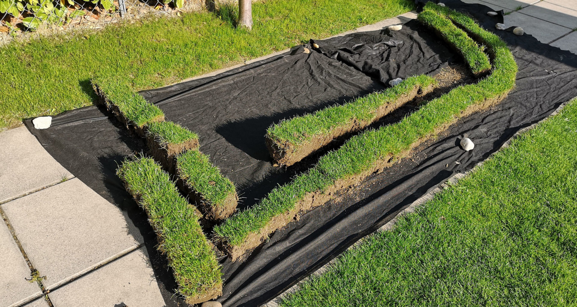
Systematically lay down turf so that you can then put them back again in the same order
The sod will only be put back in at the end of the work. So that they do not break during interim storage, you should be careful to work quickly. In my experience, the sod can withstand 3 or 4 days without any problems, probably more. It is best to wet the sod a little in between to be on the safe side so that it does not dry out.
The trench is then dug to a depth of 10 to 12 inches.
Shoveling the earth out of the trench
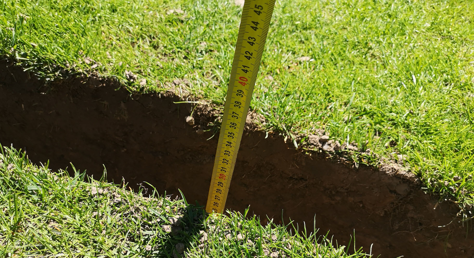
Also check the correct depth every now and then
Tip: If possible, keep a distance of at least 3 feet from larger trees, otherwise the digging work will be made significantly more difficult by the roots!
Tip: Where possible, you should avoid sharp corners in the trench as far as possible, as these mean additional water pressure loss. Instead, guide the pipes around the corners in curves that are as long as possible!
Lay the pipeline
Hang up the day before
In preparation for the work, it is advisable to spread PE pipe as large as possible on the lawn the day before the actual work. PE pipe is usually sold in rolls and is very stiff. When it is laid on the lawn and under the influence of solar radiation, this rigidity decreases and the pipe loses the tendency to want to align itself in a roll shape. This makes further laying work easier.
Mark the pipeline pipes
In order to be able to easily assign the pipeline pipes both in the course of assembly and also during excavation work taking place a few years later, I recommend marking them every 8 to 12 inches. This can be done, for example, with insulating tape of different colors. You can quickly see which sector a pipe belongs to. This is particularly important when several pipes are laid next to each other.
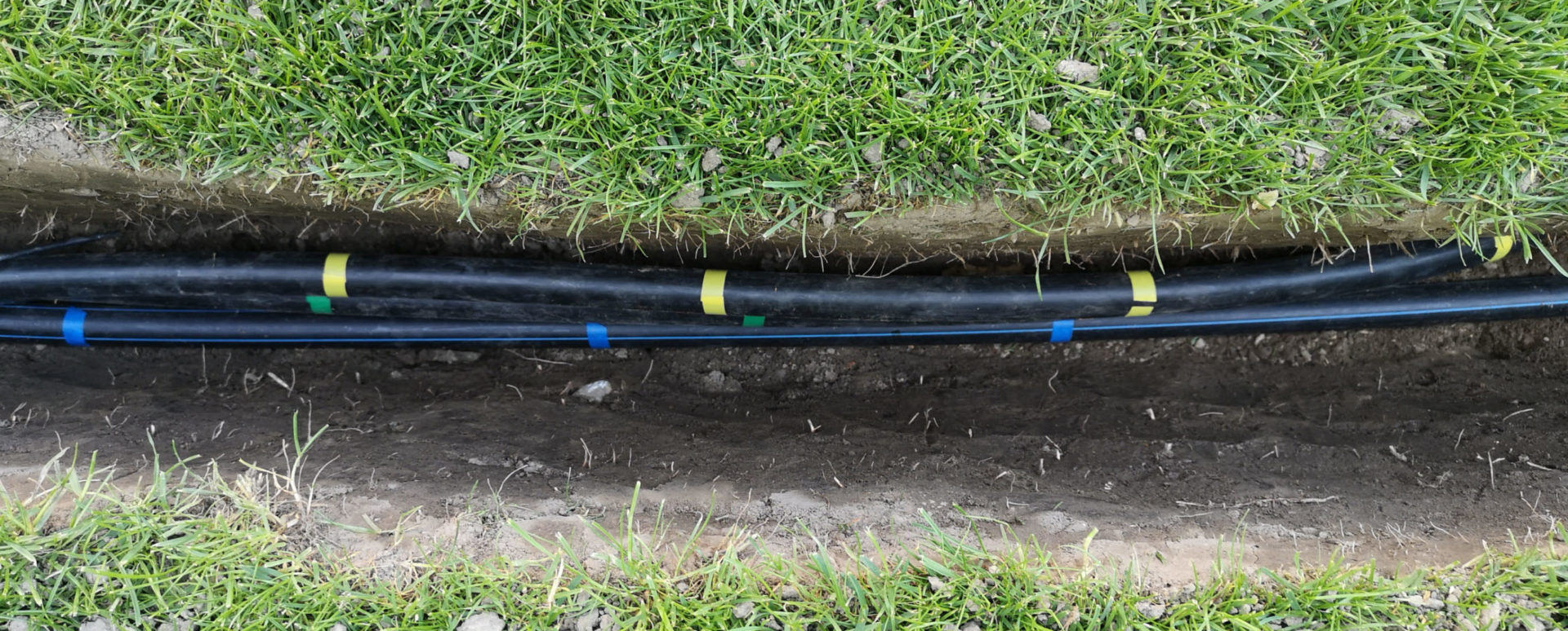
Example of marking with different colored insulating tape
Fix the pipes with ground anchors
So that the pipes do not stroll around in the trench, and above all so that they are in the right position when setting cutting marks and thus the length ratios are correct, you can help yourself with ground anchors (Amazon Link). These are knocked into the earth above the pipe and fix the pipe in the desired location. The pipe should still have a little play so that it can be tightened a little if necessary. The ground anchor should therefore only exert a little force on the pipe and under no circumstances should it press the pipe in! You can then pull it out again at the end before filling the trench and use it again the next time.
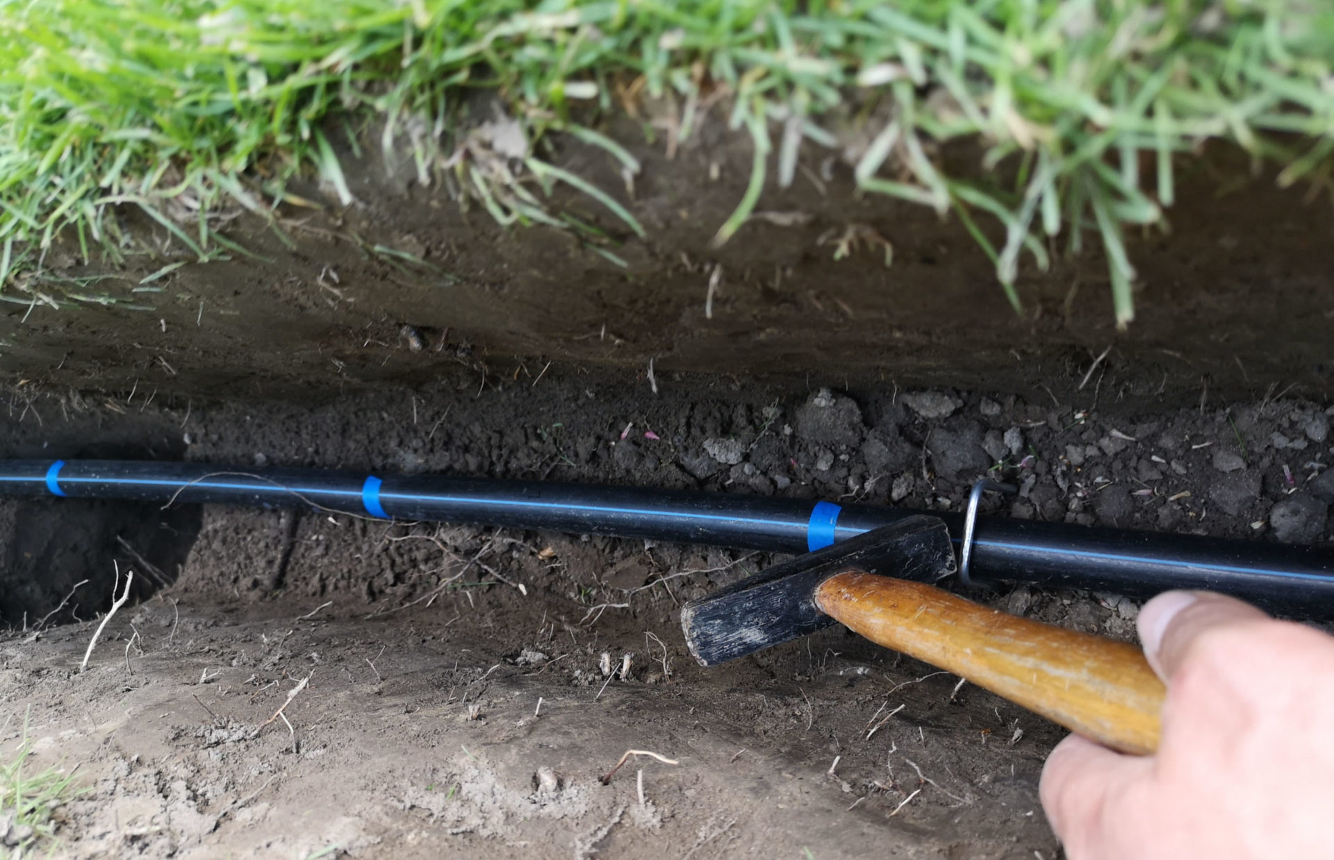
Press the ground anchors into the ground and carefully knock in the last piece with a hammer
Guide pipes around the curve
If you have planned curves in the irrigation canal, which can be useful to keep the pressure loss in the pipeline as low as possible, then you also have to lead the pipe around the curve. The PE pipes are quite flexible, but if you don’t have to, you should take the curve as gently as possible, in a large arc.
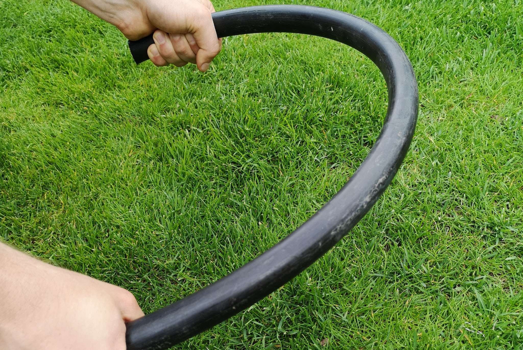
PE pipe can be bent this far and a little further
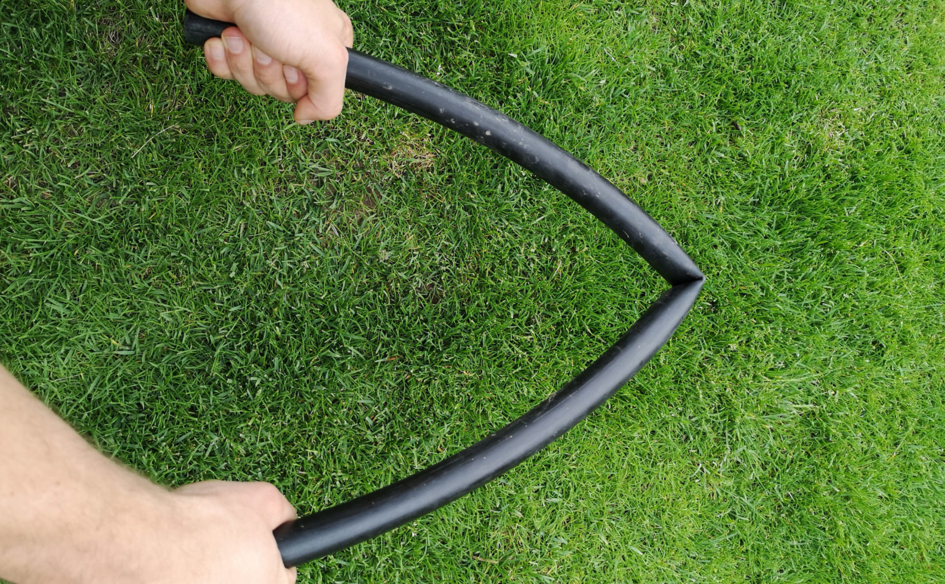
Kinked pipe must not be used in the pipeline because the kink forms a bottleneck
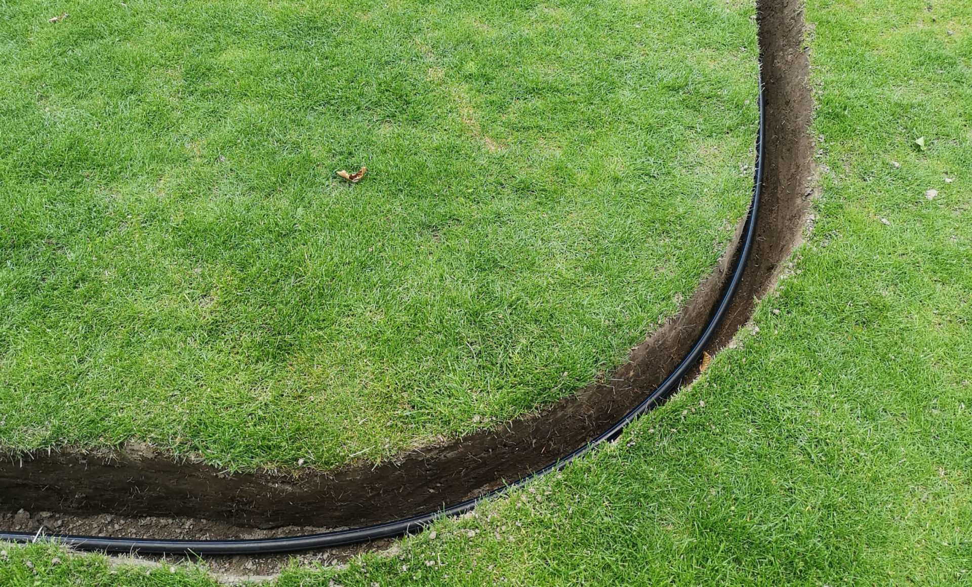
Example of a built-in curve (smoothly executed)
If, due to structural conditions, you are forced to guide the pipe around the curve in a very small radius, or if the pipe has to make several small changes in direction over a short distance and you do not want to or cannot work with elbows, then the following tip from a blog reader could be be of use to you:
In order to be able to bend the PE pipe with small radii without risk, one can close it at one end (e.g. with a rubber stopper) and then fill it completely with sand. Quartz sand, for example, is very suitable for this, which is compacted in the pipe by repeated tapping until the pipe is completely filled with sand and nothing can be poured in any more. The pipe is now also closed on the other side and it is best to make a pattern, e.g. made of wire, which specifies the desired pipe route. The pipe is now fixed, e.g. in a vice, and then that part of the pipe that is to be deformed is slowly and evenly heated with a hot air blower or a hot air gun until the pipe can be bent according to the template.
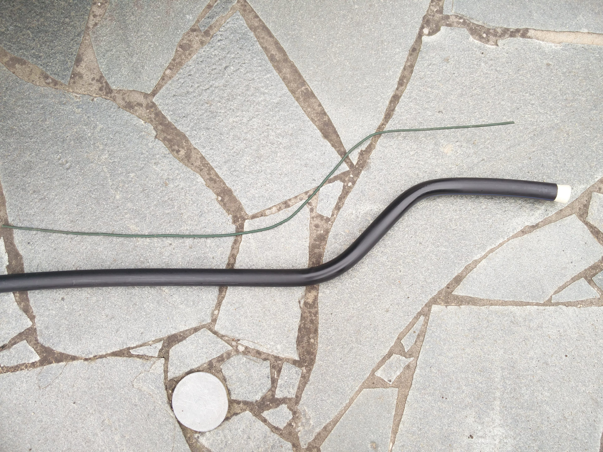
PE pipe shaped according to the method described (the wire used as a template can be seen above)
Cut pipes
PE pipe can be cut relatively easily. You can do this very well with a hacksaw or a miter saw, even easier with your own pipe cutter. It is important to ensure that the cut is as straight as possible.
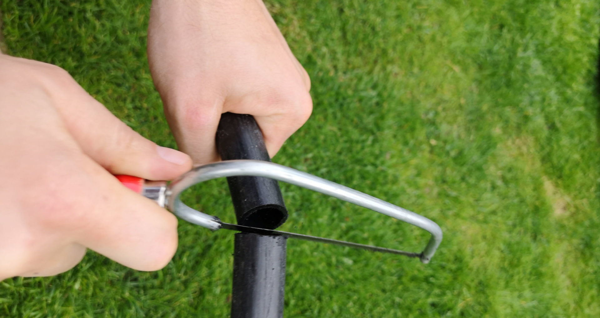
PE pipe can be cut very easily with a hacksaw
Simply file away any ridge at the cut with a file or cut away with a utility knife. Uncleaned ridges can damage the sealing ring of the connector when the pipe is pushed into a connector.
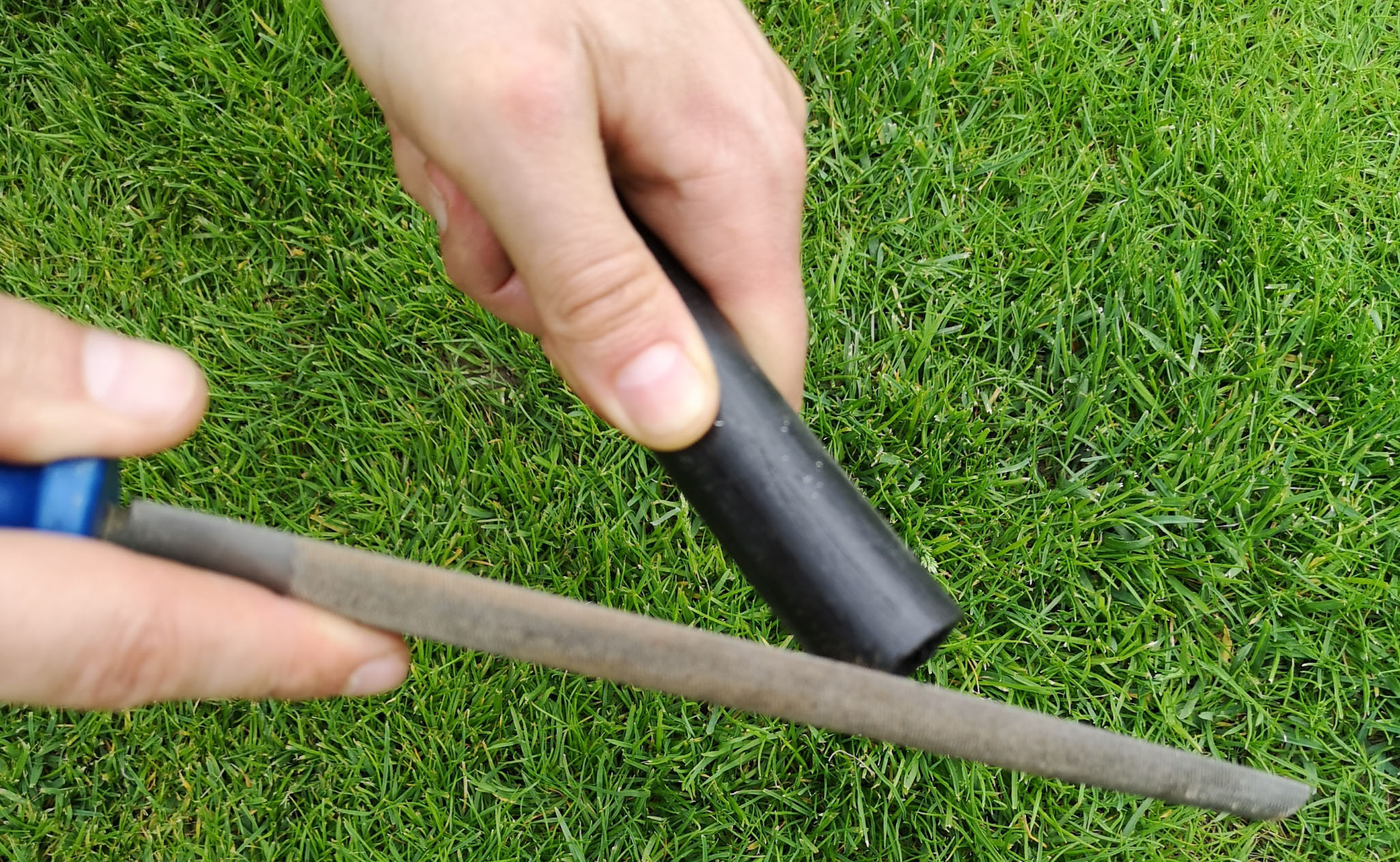
Outwardly protruding ridges should be removed
Using pipe shears (Amazon link) saves filing, as they make a very clean cut. Cutting is also very quick by hand. This is a pleasant advantage when there is a large number of areas to be cut.
Connect pipes
The pipes are connected to each other with the help of the appropriate connectors. When pushing the pipe into the connector, make sure that the pipe is pushed in far enough. The first bit, the pipe slips fairly easily into the connector and you get resistance. This is where the clamp integrated into the connector begins. With a little effort, the connector can now be pushed a few centimeters further into the clamp until it is really in place.
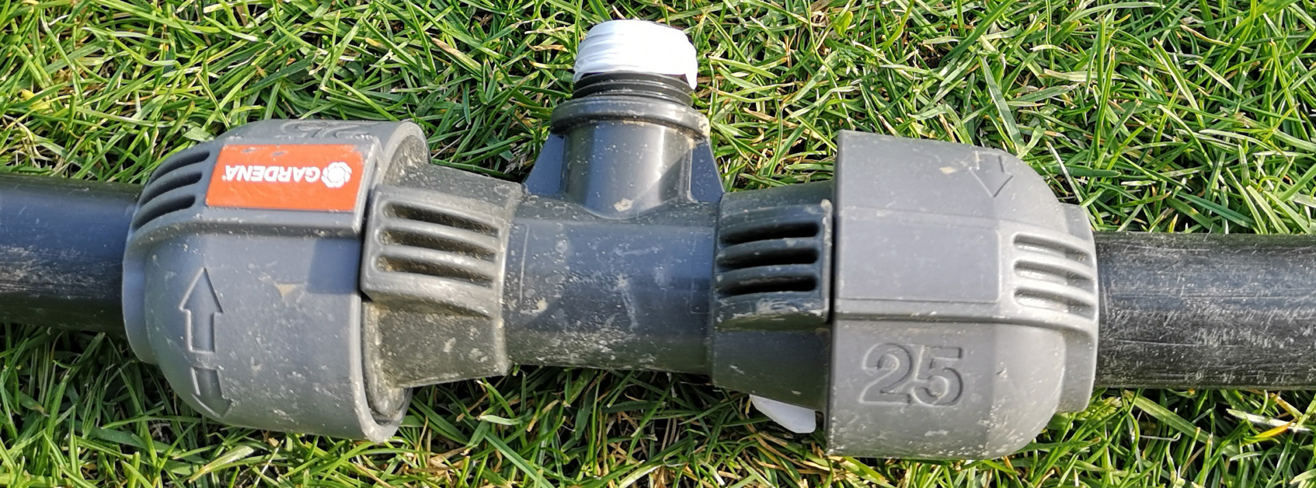
The following two images demonstrate this using a Gardena connector:
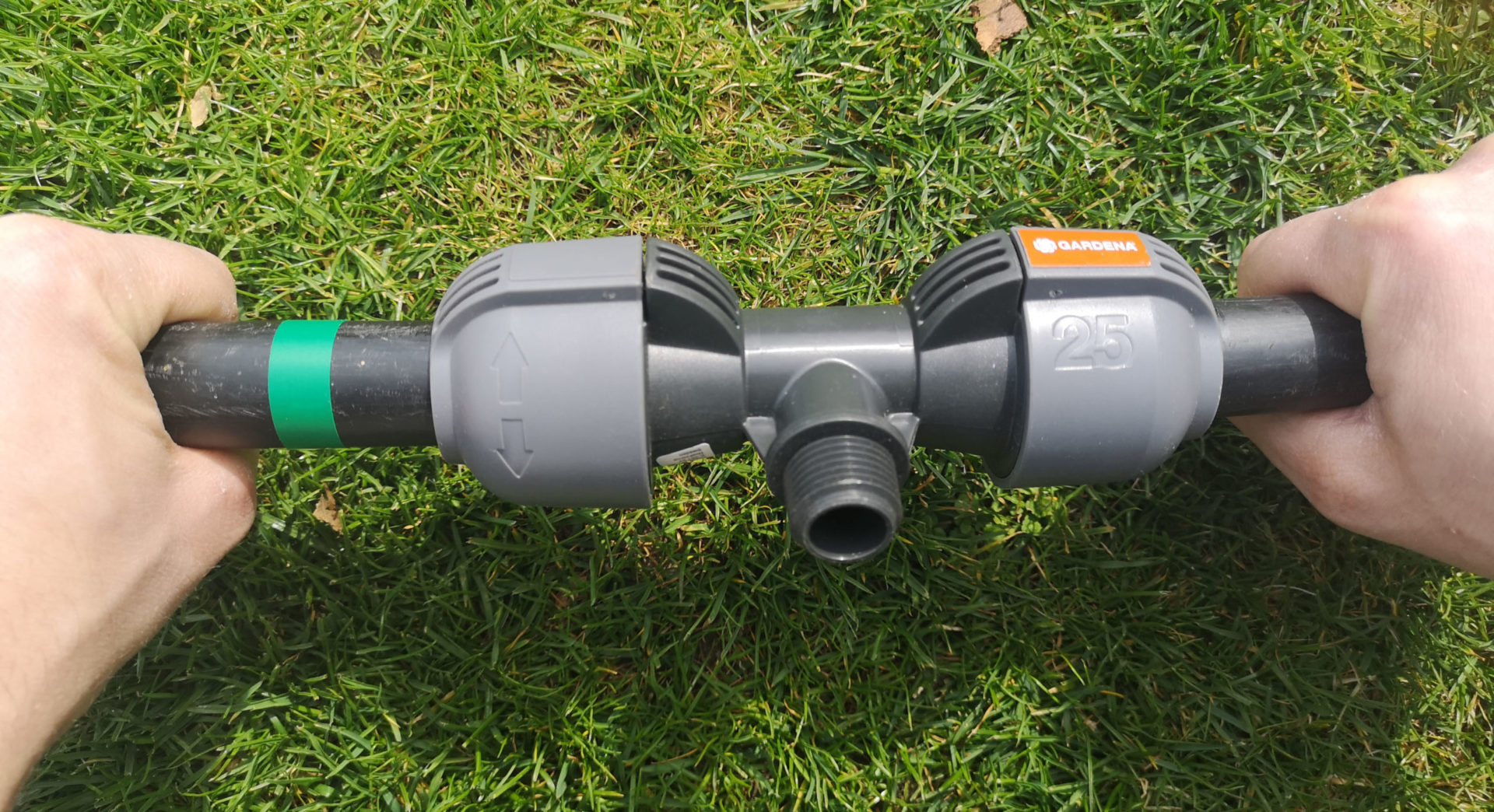
This is where the left pipe is attached to the clamp of the connector
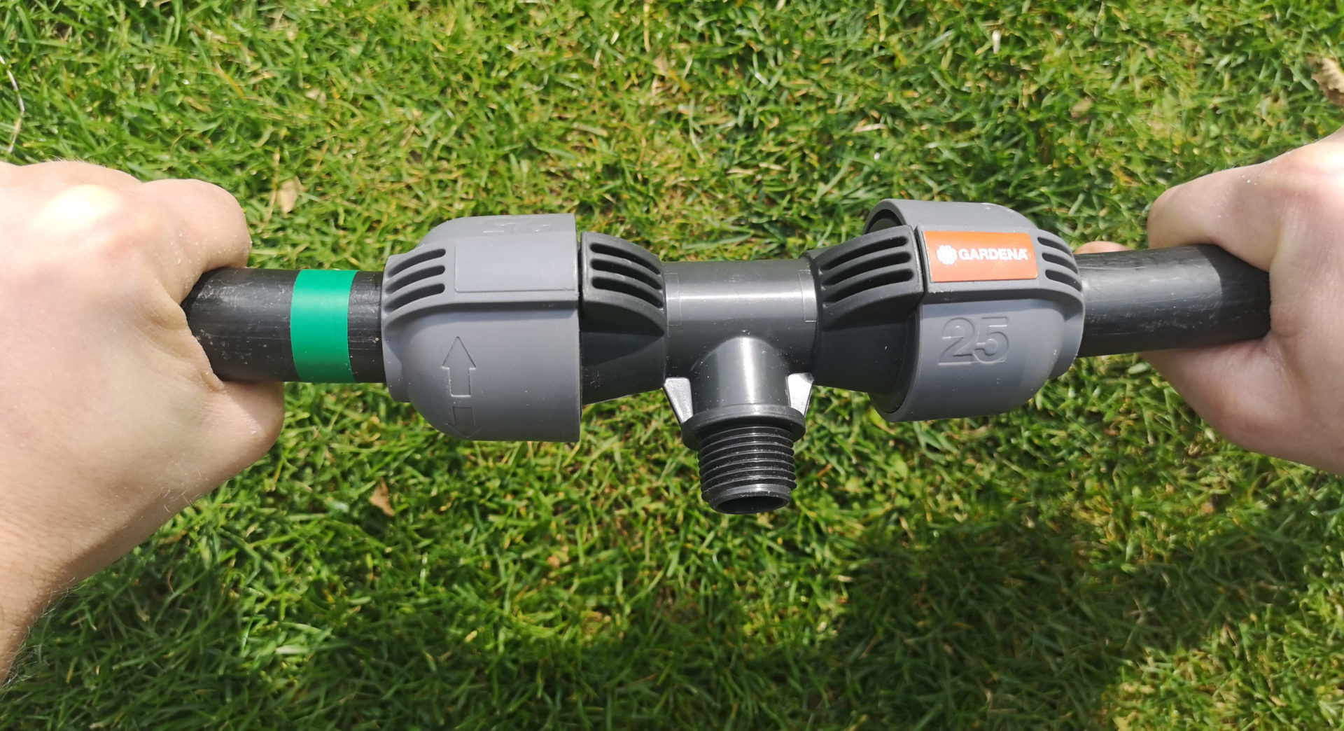
With a little force, it can be pushed a little further into the clamp (easily visible on the green marking on the tube)
When assembling the pipeline, also make sure that no soil gets into the pipes!
Connect sprinklers
There are basically 2 ways to connect a sprinkler:
- Connection via a connector directly to the pipeline
- Connection via a flexible swing joint
In the first variant, the sprinkler is screwed directly to the pipeline in the connector provided for this purpose. In the second variant, a connector is also attached to the pipeline. However, the sprinkler is not connected directly here, but via a swing joint connected to the connector. This is a flexible connector between the pipeline and the sprinkler that can be aligned in any direction, making sprinkler installation easier and more flexible. In the blog post on Swing Joints, I explain in detail what advantages this has, which variants of Swing Joints there are and how to install them correctly.
Below is a brief comparison of the two connection types:
Connection directly to the pipeline
Here the pipeline is interrupted with the appropriate sprinkler connection connector. An extension piece with a sprinkler connection is used on a straight piece of pipeline, an L-piece with a sprinkler connection is used in a corner and an end piece with a sprinkler connection is used at the end of a pipeline line. These connectors are offered with 1/2 inch or 3/4 inch male threads, depending on whether you are using sprinklers with a 1/2 inch or 3/4 inch connection.
The connection is made in the following way:
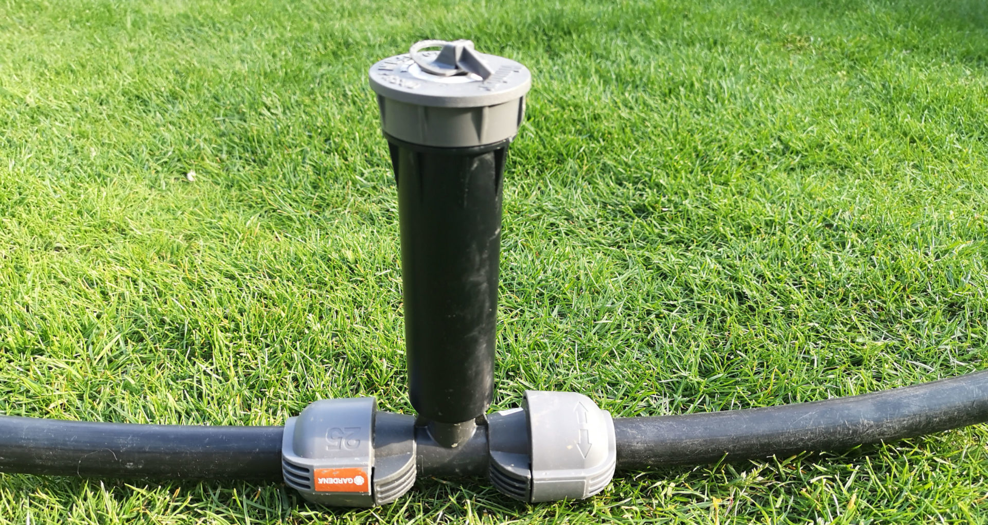
Dry run: This is how the sprinkler is connected to the pipeline
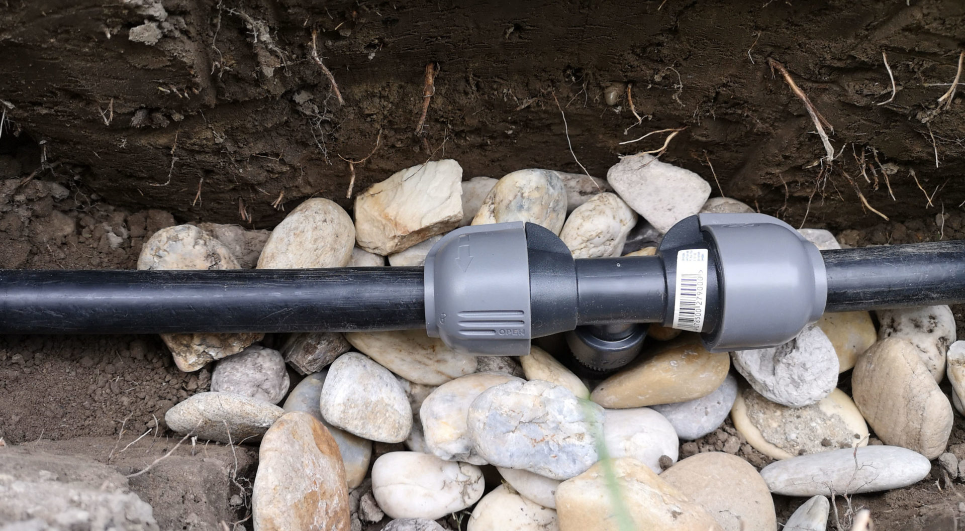
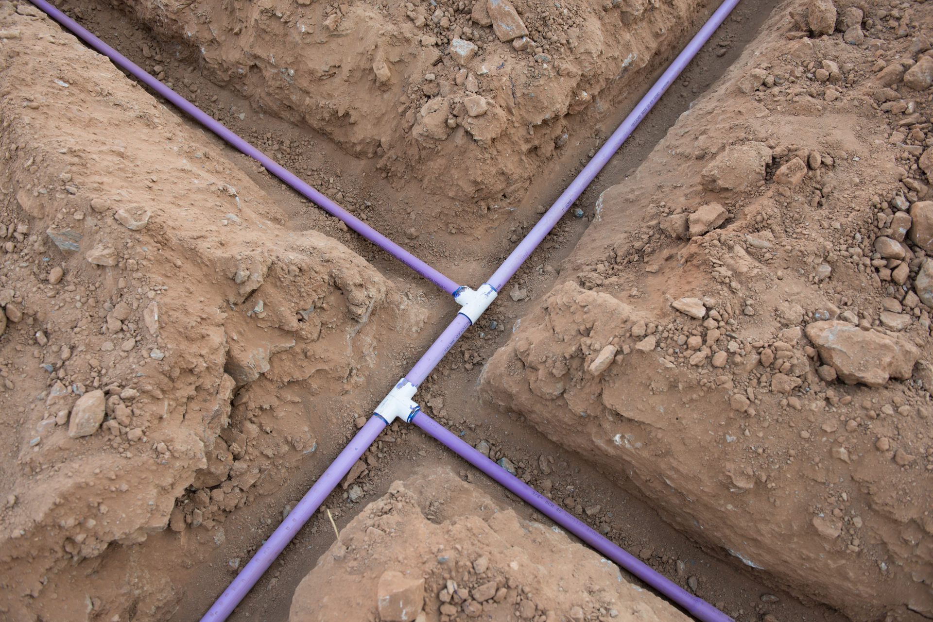
And here is an example image in the excavated trench:
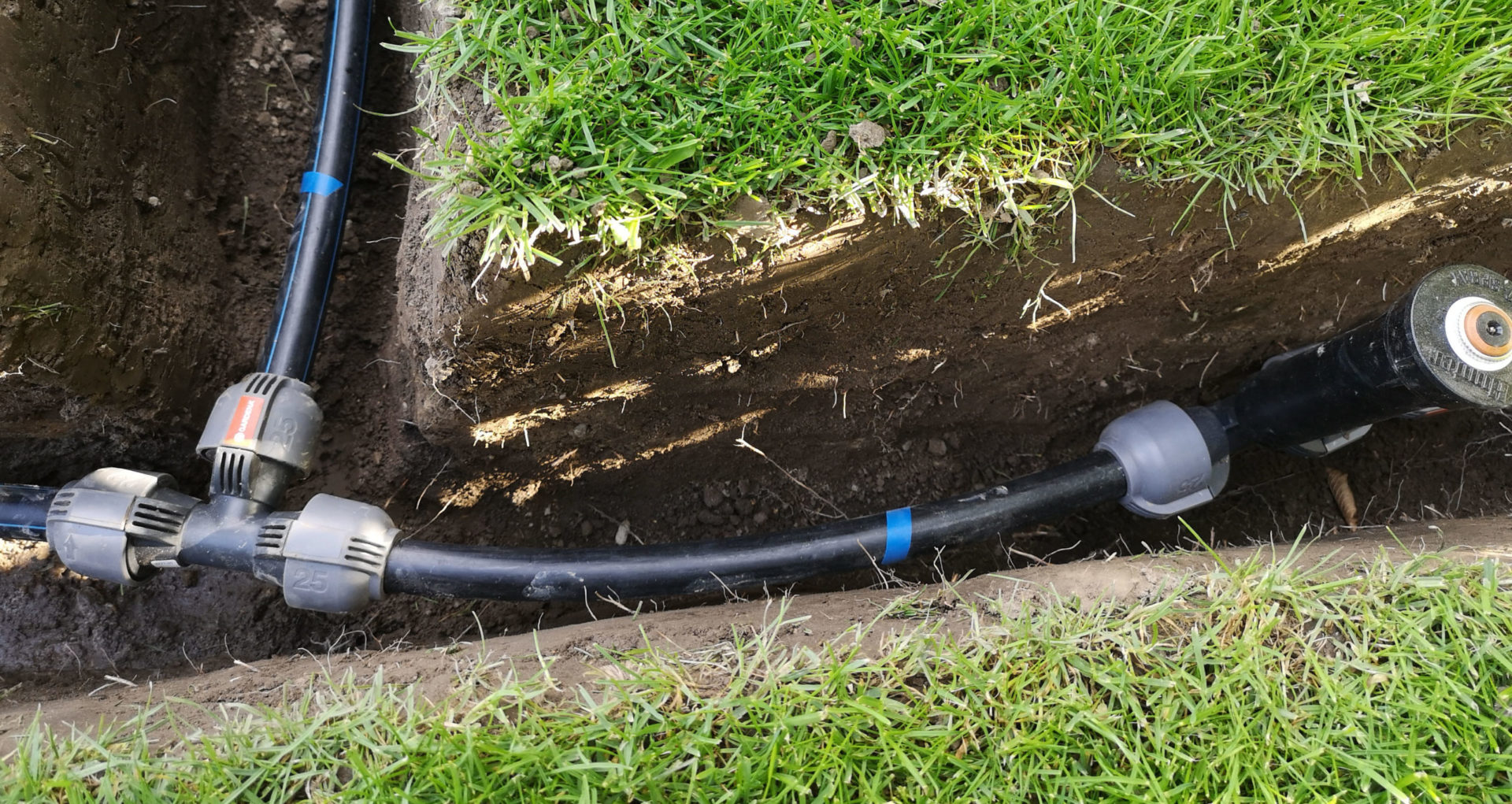
Pipeline line branching off from T-piece with connected sprinkler
Connection via a swing joint
With this variant, too, you first have to interrupt the pipeline with a sprinkler connection connector. Only here you don’t use a connector with an external thread, but one with an internal thread. And such connectors are only available with a 3/4 inch internal thread connection. Alternatively, you can also use a so-called “tapping clamp”. With this, the pipeline pipe is not interrupted, but the clamp is screwed onto the pipe and then a hole is drilled into the pipe at the point specified by the clamp. Further handling is the same as with the connector.
The swing joint is connected to the 3/4 inch internal thread connector. As with the direct connection variant, it is important to pay attention to the connection size of the sprinkler:
- 1/2 inch sprinkler: You need a 3/4 inch to 1/2 inch swing joint
- 3/4 inch: You need a swing joint 3/4 inch to 3/4 inch
The swing joints are also available in different lengths (6 inches or 12 inches) and made of different materials: hard plastic or soft tubing. In the case of the hard plastic variant, the flexibility is achieved through flexibly rotatable joints. The flexible hose version can be purchased fully assembled, or you can buy the flexible hose and fittings separately and assemble the swing joint to the desired length yourself. This variant is practical if you need a longer connection than the 12 inches offered as standard.
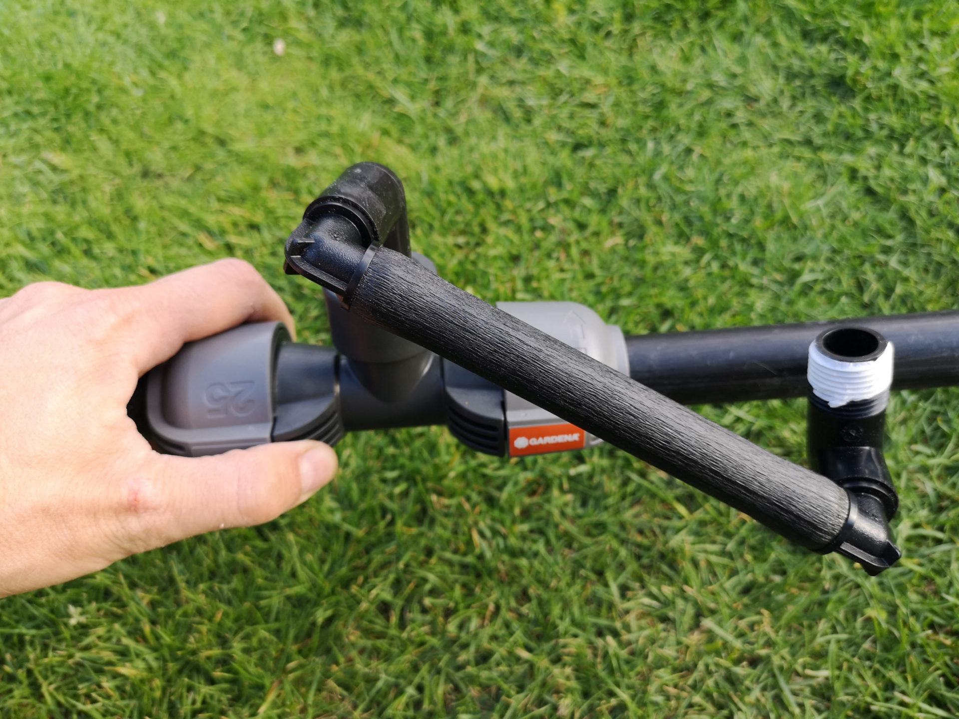
The following picture shows an example of how to connect a swing joint:
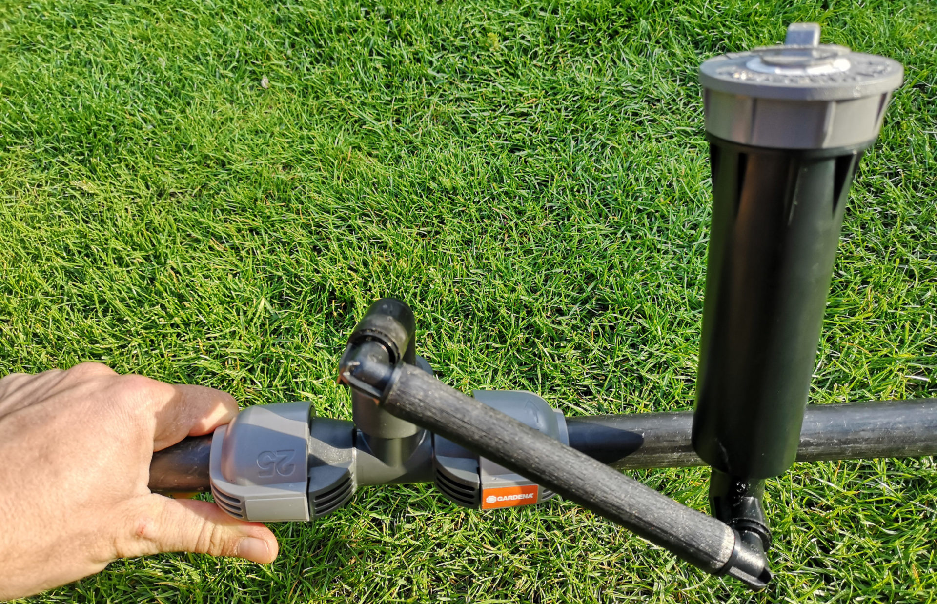
Hunter hard plastic swing joint with a length of 6 inches connected to a female thread connector
And in the ditch it looks like this:
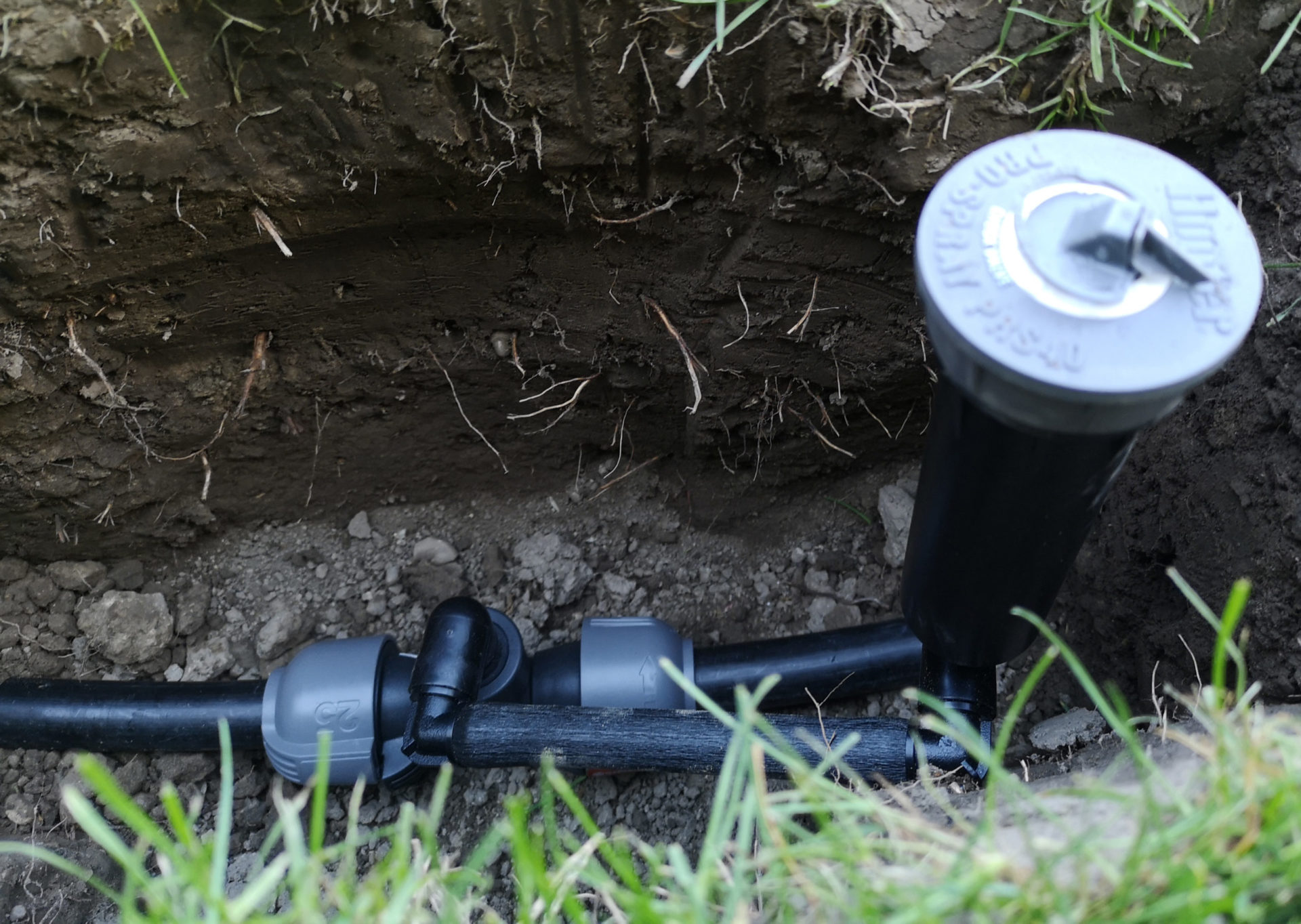
Same swing joint as before hooked up in the trench
You can find more assembly examples and an overview and comparison of the swing joints available on the market in the following article:
Installation depth of the sprinkler
With both variants, i.e. installation directly on the pipeline pipe or via a swing joint, care must be taken to ensure that the sprinkler is installed at the correct depth, i.e. the sprinkler head is flush with the ground level. Or even better, minimally, about 0.2 inches above! This way you are on the safe side, both in terms of damage caused by the lawnmower and contamination from softened soil: the lawn is usually mown at a height of 1.5 or 2 inches, with rotary mowers 0.8 inches is also possible. The 0.2 inches that the sprinkler sticks out of the ground are therefore not a problem. And they are so high that when it rains, the soil does not spill onto the sprinkler head, so it is “covered” with soil.
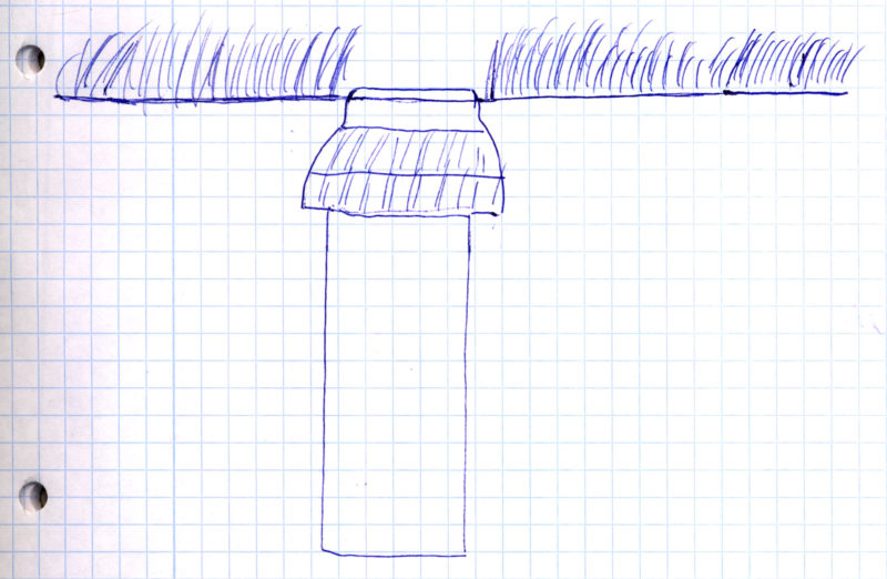
This is how it is ideal: The sprinkler head closes slightly above ground level
When installing the sprinkler directly on the pipeline pipe, the correct installation depth may need to be established by adjusting the pipe height at the sprinkler connection point. If the pipe is too deep, then it must be lined with earth at the sprinkler connection point as far as necessary for the correct installation height. When connecting with a swing joint, such corrections are not necessary, the sprinkler is simply brought to the correct depth and position when filling in the trench. In both cases, however, the final positioning does not take place at this point in time, but only after the lines have been flushed through and the test run to check the tightness of the connections has been carried out (see menu item “Perform test runs“).
The sprinkler head should be very slightly above ground level
Seal thread
In practice, it is also done without and most manufacturers do not make any specific statement on this subject, but I recommend sealing with Teflon tape wherever two threads meet. It’s quick, just wrap the Teflon tape 3 to 4 times around the thread and you’re on the safe side that nothing leaks. This applies to the connection of sprinklers and swing joints and subsequently to all other elements with a threaded connection. Caution: Some sites and manufacturers warn against using hemp instead of Teflon tape for sealing. The hemp fibers can easily slip on the plastic thread and deform the thread due to their comparatively large volume.
The thread of the connector should be wrapped with Teflon tape before connecting the sprinkler
Lining with gravel
A few manufacturers like Gardena state in their descriptions that the sprinklers have to be lined with gravel. This is not my experience and the big international manufacturers like Rain Bird and Hunter do not recommend it either. In my opinion, lining with gravel only makes sense for components that are open at the top and into which rainwater can enter. For example, valve boxes, water sockets or junction boxes, or components that direct water directly into the ground, such as drainage valves. On the other hand, no gravel is necessary/useful below sprinklers.
Optional: Installation of a drain check valve
This point is only relevant if you install the sprinklers on a slope. If the difference in elevation between the highest sprinkler and the lowest sprinkler exceeds 6 feet, the pipeline will drain after the lowest sprinkler has finished watering. This leads to unsightly puddling and silting up on this sprinkler and wastes water.
This phenomenon is easily remedied by installing a drain check valve on the lowest sprinkler. The valve ensures that water can only flow through the sprinkler when the irrigation is running. When the irrigation is finished and the pressure drops, it closes and no more water can flow through. Either you buy the sprinkler already in the variant with an integrated check valve, as is offered with some sprinkler types (see sprinkler overview) or you buy the check valve separately and retrofit it. For some sprinkler types there are specially designed check valves for this sprinkler type, which can be installed in the sprinkler body. Alternatively, a sprinkler-independent drain check valve is available with the Hunter HCV, which attaches to the underside of the body between the body and the pipeline.
The check valves differ in the maximum height difference that they allow. Usually 10 feet are possible, the Hunter HCV can be variably adjusted to up to 30 feet. Why variable? There is some pressure loss associated with the use of a check valve. The valve only lets the water through the sprinkler above a certain pressure, so a certain resistance has to be overcome. The greater the difference in height, the greater this resistance must be set and the greater the pressure loss.
For this reason it makes no sense and would even be counterproductive to use a check valve on a sprinkler where it is not necessary. A drain check valve is only used when there is a drain on the lowest sprinkler due to a height difference, otherwise not.
Special case slope irrigation
Irrigating on an incline is a very special case. The puddling issue has been addressed in the Check Valve section above, but there are a number of other considerations. There is very little literature on this. If you are faced with this problem and would like to delve deeper into it, I recommend reading the following document by Hunter on the subject of slope irrigation. In this, essential findings from practice were compiled. Here are a few key excerpts:
- For slope irrigation, you should use sprinklers with not too high precipitation rates. Definitely no sprayers. The ground must be able to absorb the water before it flows down the slope.
- When it comes to slope irrigation, Hunter differentiates between sprinklers that are positioned in the slope and sprinklers that are positioned at the bottom of the slope or at the top of the slope.
- Sprinklers that are positioned on a slope should not be installed vertically (= like letting a stone dangle from a ribbon), but at the incline of the slope. And strictly speaking, not at a right-angled 90 degree angle, but slightly more inclined towards the slope. For example, if the slope has an incline of 20 degrees, then the sprinkler would have to be tilted an additional 10 degrees (= half the incline of the slope) towards the slope, starting from the perpendicular position.
Positioned at the foot of the slope, the sprinkler is installed vertically but slightly tilted away from the slope.
The sprinkler positioned at the top of the slope is installed like the sprinklers positioned on the slope.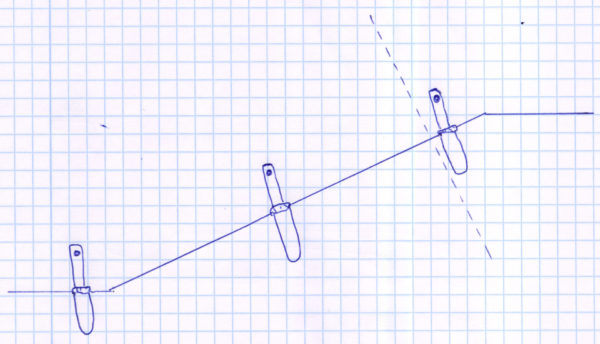
Sample sketch for sprinkler placement at the bottom of the slope, at the slope, and at the top of the slope
An alternative variant for the sprinkler placed at the top of the slope is to use short-radius nozzles instead of the normal nozzles and to mount the sprinkler on the flat instead of on the slope.
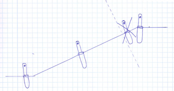
Alternative variant with short-radius nozzles in the sprinkler at the top of the slope
- The use of swing joints is highly recommended for mounting sprinklers on slopes. In this way, you can flexibly align the sprinklers at a different angle of inclination than the pipeline.
- For slopes greater than 10 degrees, decrease sprinkler spacing down the slope by 1% for each degree greater than 10 degrees. For example, if the slope is 20 degrees and the sprinklers are spaced 26 feet apart, then that spacing would be reduced by 10% to about 23 feet.
Install drainage
There are two ways to protect the pipeline and attached built-in parts from frost:
- Installation of drainage
- Annual irrigation blowout before winter with compressed air
This point is therefore only relevant if you have opted for the first option, i.e. the installation of a drainage system.
The drainage must be installed at the deepest point of the pipeline. This point is either created automatically due to a natural gradient in the area to be irrigated, or it must be created manually by digging the pipeline trench deeper at this point. One valve/ball valve must be installed for each pipeline line. If you have e.g. 6 sectors, then you also need 6 drainage valves/ball valves.
Drainage can be installed in 2 ways:
- With an automatic drain valve
- With a ball valve that can be opened manually
Installation of an automatic drain valve
A drain valve is a valve that is open in principle, but closes at a certain water pressure. If you start watering, it closes so that no water can escape. As soon as you stop watering, it opens and automatically drains the water in the pipeline. This means you always have an empty pipeline, except when irrigation is running, and you don’t have to worry about frost damage to the pipeline.
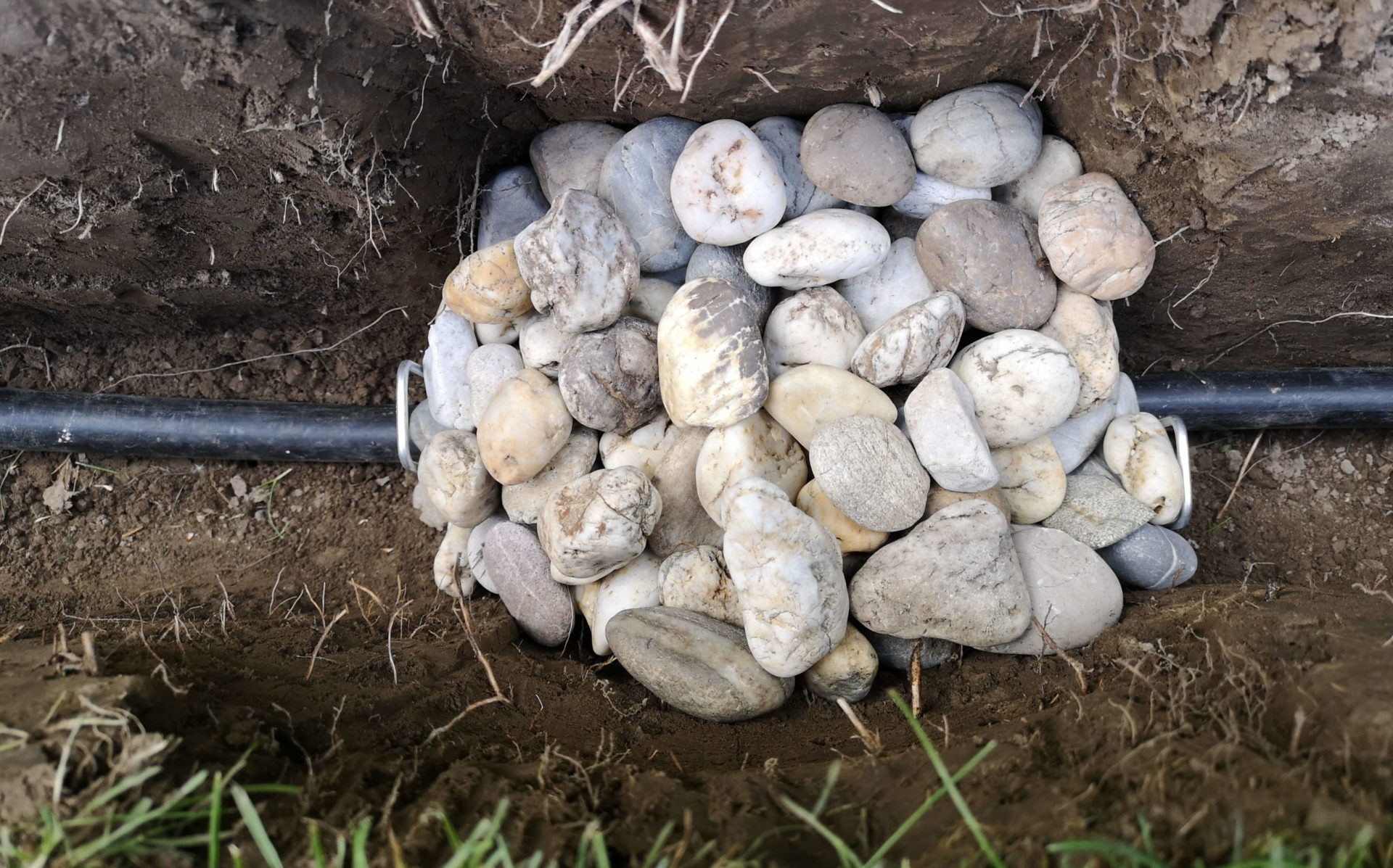
The drain valve is installed in a cube of gravel 8 to 12 inches in length, width and height. For this purpose, a corresponding bulge must be dug at the deepest point of the pipeline and filled with washed gravel. The gravel should be at least 0.3 inch in diameter. The drain valve is placed on the gravel. It is connected via a connector or via a tapping clamp.
Drain valve placed on gravel
Optionally, the gravel packing can also be wrapped with a filter or drainage fleece in order to have the best possible protection against the ingress of dirt or root growth. Finally, after the function test has been carried out, the drainage valve is also covered with gravel from above. You can support the side with tools such as ground anchors in order to achieve a cube-shaped heaping up.
Finished gravel pack around the drain valve
Further information: Blog post on the installation and the advantages and disadvantages of a drain valve
Installation of a ball valve that can be opened manually
This works in a very similar way to the previously described installation of an automatic drain valve: the ball valve is also installed at the lowest point in the pipeline. And it must also be lined with gravel so that the water can drain off quickly and easily. However, the ball valve is not covered with gravel and earth, but remains freely accessible from above. To make this possible, it is installed in a valve box.
Valve boxes are open at the top and have a cover, so the line can be emptied simply by manually opening the ball valve before the cold season begins. Just like a drain valve, the ball valve is simply installed in the pipeline using a suitable connector.
Compared to the automatic drain valve, this variant has the advantage that it is possible to check correct functioning at any time and to replace the tap if it is not working. This is not so easy with the drain valve, as it is installed underground and cannot be reached. However, this type of installation in a freely accessible box can of course also be used for a drain valve. The second advantage of drainage using a ball valve is that the water is not drained after every irrigation, but only once a year. As a result, less water is wasted unnecessarily.
Install a water socket
Water sockets, or hydrants, are not a must in an irrigation system, but they are very practical in everyday life. Regardless of the actual water source, they act as additional water connections in the garden, from which water can be tapped directly or a hose can be connected. With this you can also compensate for the disadvantage of a water source that is not centrally located by placing the water socket exactly where you need it in everyday life.
There are three types of water sockets on the market: those with a water stop function, to which you can simply connect the hose, those that are put into operation with a suitable key, and valve boxes, where you open a water tap. I present the different types of water sockets in detail in the following blog post.
Even if you want to install a garden shower in the garden, I recommend using the water socket instead of connecting the shower directly to the pipeline with a hose. So integrate the water socket into the irrigation system and then the last piece away from the water socket with a hose to the garden shower. This way you can easily change something later if the worst comes to the worst.
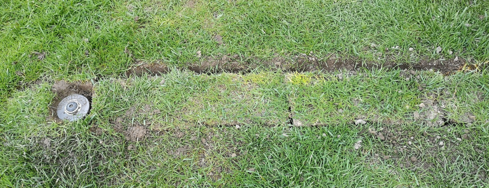
A separate pipe string is laid in the trench to supply the water socket. This will later be connected to the water source bypassing the controller. You do this so that the water socket pipeline is always under water pressure, i.e. it is always ready for use. In contrast to the other sectors of irrigation, which are activated only temporarily. If more than one water socket is planned, then these are connected to a common pipeline. The water outlet is installed very minimally, 0.4 inches above ground level. So that no dirt gets in and the lawn mower can drive over it.
Connect Micro-Irrigation
Since the micro-irrigation usually takes place on the surface and can therefore still be designed after the ditch has been filled in, it is sufficient to connect the pressure reducer to the micro-irrigation pipeline for the time being. And it is best to attach a short piece of drip hose or a short piece of hose with sprayers to each pressure reducer so that the basic functionality can be tested before filling up.
Perform test runs
Even before the ditch is backfilled, I recommend doing the following actions and tests to make sure everything is working properly. At this stage it is still very easy to correct, later it is much more complex.
Step 1: Flush the line
This is a precautionary measure in case, despite being careful, earth has fallen into the lines. The pipeline is connected to the water supply and the end of the pipeline is opened (or multiple ends in the case of a branching pipeline). Water is then allowed to flow through so that impurities are flushed out at the open end. To be on the safe side, let the water run for 2 or 3 minutes and repeat the process for each sector! This measure is particularly important for micro-irrigation sectors, as these are more difficult to clean themselves due to the low pressure.
Step 2: Test run tightness
In the second step, it is checked that all connections are tight, i.e. that water does not escape at any interfaces in the pipeline. In particular, the connections of sprinklers, drain valves, water sockets and other components as well as the connectors for diverting or dividing the pipeline must be carefully inspected. In this step it doesn’t matter how the sprinklers irrigate, that will be checked in the next step and should not distract us unnecessarily.
Tip: If the type of sprinkler used allows it, turn off the watering on all sprinklers during the inspection so that you are not distracted by the water leaking from the sprinkler! If the sprinkling bothers you too much or you don’t want to get wet, you can make a protective shield or put buckets over the sprinklers.
Note: The leak test is the most important step, because after the trench has been filled in you can no longer see the pipeline and subsequent troubleshooting means more work! Check everything carefully, there must not be even a small leak of water anywhere!
Step 3: Fix the sprinklers
Before the last test run, the sprinklers must be brought into their correct position (see point “Installation depth of the sprinkler”). To do this, tamp the sprinklers down with some earth or press the earth down by hand so that the sprinklers are fixed in their straight position, flush with the ground level, and can no longer slip.
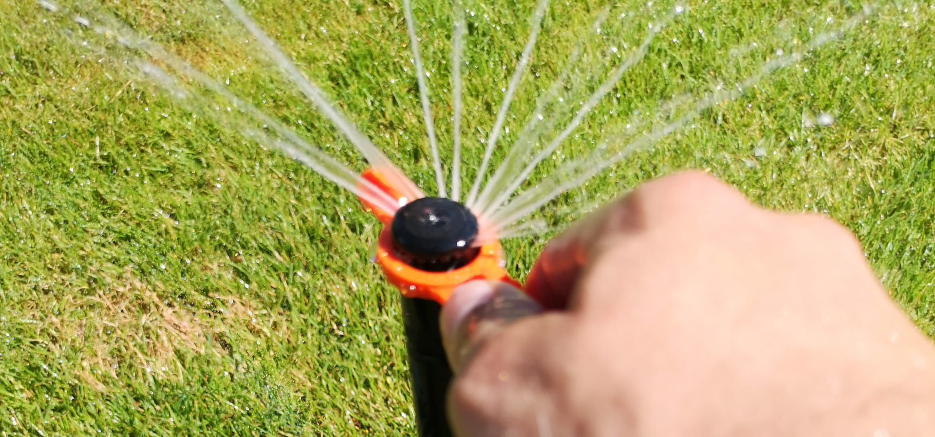
Step 4: Test run to test the functionality of the sprinklers and other components
In the final test run, it is checked that the connected sprinklers are working correctly. This is just a matter of checking that the sprinklers are basically working and that they are meeting the expected throw distance. The fine adjustment of throw distance and irrigation sector only takes place at the end, after the trench has been filled in.
Then carry out the functionality tests for the other components as well: Check that the drain valves drain the water correctly when the irrigation stops and that the water extraction from water sockets works correctly. Test-connect drip lines and other micro-irrigation components.
Additional tip: Before you fill it up, take plenty of photos that document the course of the ditch and the neuralgic ramifications and junctions and keep them safe. After a few years you can no longer remember all the details and so you can always see what it looks like underground if extensions or necessary repairs arise.
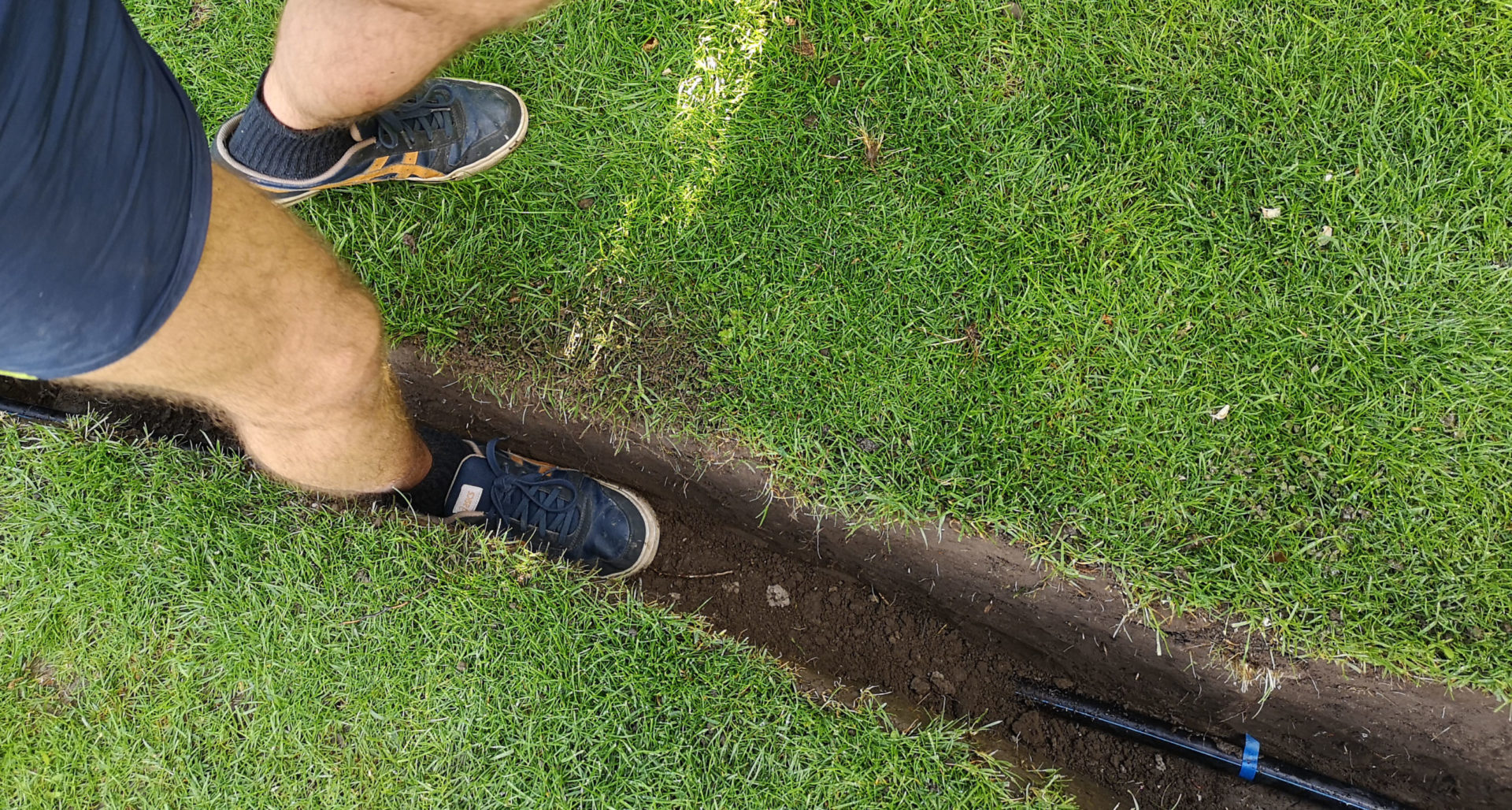
Fill in ditches
Now the trenches are being filled in again. Be careful initially around the sprinklers and the points where connectors and components are connected so that the sprinklers and components are not displaced from their intended position. It is best to tamp down the earth layer by layer in several stages so that it compacts well.
Shovel soil into the trench in layers and tamp down
The earth should be flush after the trench has been filled. But since, in my experience, it sinks a little in the days that follow, despite all the compaction, I recommend piling it up a little bit higher so that the earth above the ditch protrudes slightly above the surrounding level.
If you have kept a lawn sod for later re-insertion, the trench should be filled up less high and then the sod put back on and pressed down firmly. Here, too, this should be slightly above the level of the surrounding lawn after pressing on. The sod is to be cut out at those places where sprinklers are placed.
Replanted sod. Between the individual pieces of sod and at the edges, free spaces are then to be generously filled with soil.
Connect controller
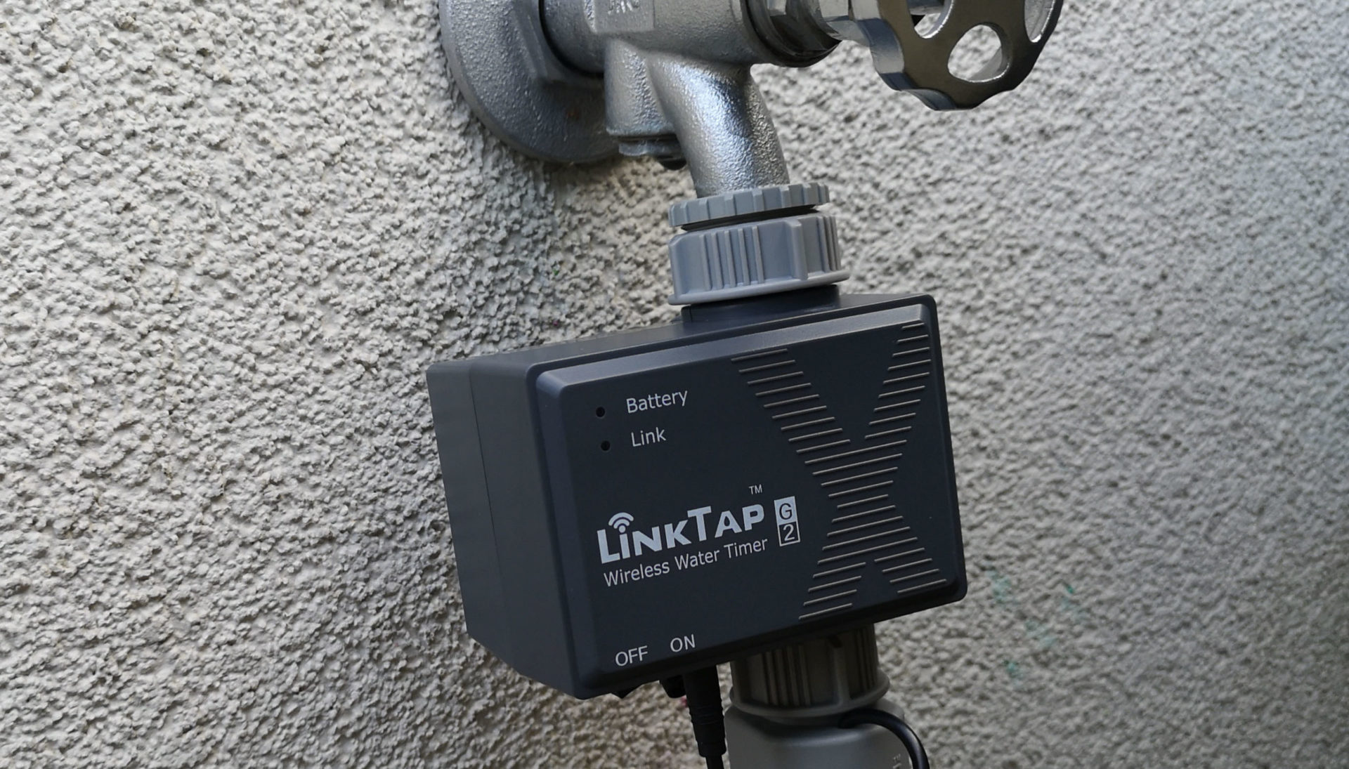
At this point, the control of irrigation is installed. This can be purely mechanical control or control via an irrigation computer. When using an irrigation computer, additional sensors can be used to optimize irrigation. Since there are very extensive options here, this step is dealt with in a separate menu item “Controlling”. In this you will also learn more about the different methods by which you can control your irrigation and what options there are for automation and the integration of your control into a network.
Adjust sprinklers
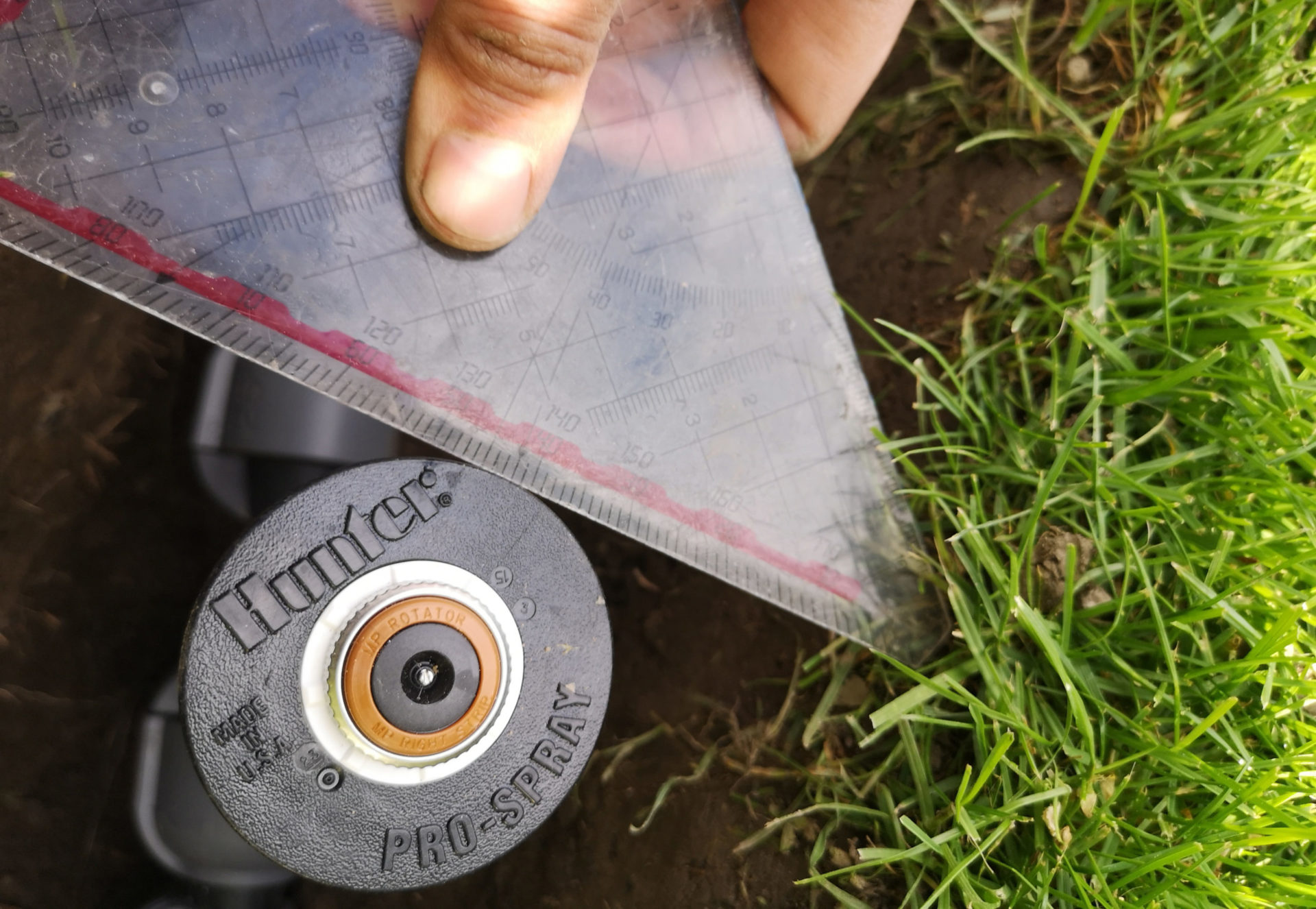
Now that the surface is back in order and the controls are in place, fine tuning can begin. The sprinklers or sprayers are now set exactly to the planned range and to the planned circle sector. The setting works slightly differently depending on the type of sprinkler, but the basic principle is always the same: The range of the sprinkler can be reduced using an adjusting screw. As a rule, a reduction of up to 25% is possible. Depending on the sprinkler model, the circular sector to be irrigated can be set within the specified range.
Both settings are always possible with the models I know with a normal screwdriver. The manufacturers also sell practical adjustment keys that make things a little easier. From my point of view, there is nothing to be said against it, these auxiliary tools are sold cheaply, for mostly 2 to 3 dollars, and work well. Just beware of grossly overpriced listings where these tools are often sold at multiples of their price.
Adjusting an MP rotator with the associated adjustment key
Setup Micro-irrigation
Drip hoses are simply placed on the ground. They shouldn’t be buried in the ground, but in my experience covering them with a bit of light bark mulch isn’t a problem. For optical reasons, however, it is often enough to cleverly thread the drip hose behind bushes or hedges so that it is practically no longer visible.
In a hedge or a row of bushes, the drip hose is laid in a long line along the trunks of the plants. On the other hand, if you want to water an entire vegetable patch with a drip hose, the hose is laid in rows at least 1 foot apart.
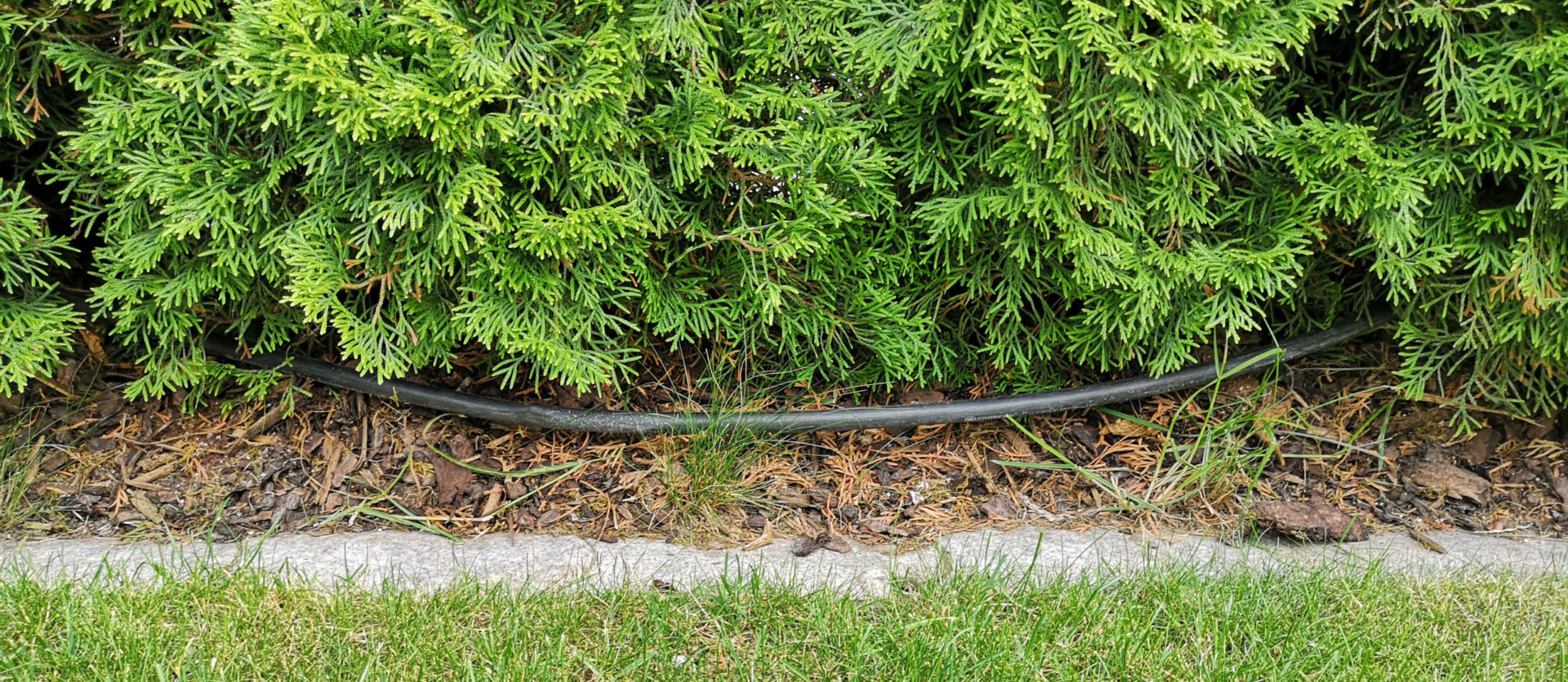
Drip hose laid in hedge
If you want to water individual flower boxes and pots, then you run the micro-irrigation pipeline to the place where it is happening and from there you let optically less conspicuous distribution pipes with a much smaller pipe diameter branch off into the boxes and pots.
If you don’t want a hose lying around because the area is constantly being walked on, or if it is important to water from above, then micro-irrigation sprayers are ideal.
A comprehensive overview of the various components that can be used in the context of micro-irrigation can be found in the following article:
Blog post: Areas of application and components of micro-irrigation
Archiving documentation
The last point is easy to overlook, but it is essential in order to be prepared for all eventualities in the future and to be able to make extensions/repairs as easily as possible. Archive all essential information about your irrigation system! These are in particular:
- The plan according to which the irrigation was created
- This includes all changes made to it during assembly
- Your assumptions about water pressure and volume (if these are not clear from the plan)
- Invoices for the ordered products
- Product Descriptions
- Photos of the pipeline and connections taken during assembly
Either printed out in a project folder or electronically archived. In the case of electronic archiving, in addition to the local backup on the computer, a backup should be created on a mobile data carrier (USB stick) or the plan should also be saved in the cloud so that the data is not lost in the event of a device defect.

Functionality and installation of a drain valve
Drainage valves are used to protect the irrigation system from frost. The following article explains how this works, what advantages and disadvantages it has and what alternatives there are. Depending on the climate at [...]
How swing joints work and how they can be used
Swing joints simplify the connection of sprinklers to the irrigation pipeline. Instead of being connected directly to the pipeline, the sprinkler is connected to the pipeline via an intermediate piece, the swing joint. The [...]
PVC or PE pipe: which one is better for an irrigation pipeline?
While PVC pipes are traditionally used on the west coast of the USA, PE pipes are primarily used on the east coast. In Europe, almost exclusively PE pipes are used, in Australia both systems can [...]