How to control your irrigation system
This page provides information about the manual and automatic options for controlling an irrigation system.
Ways to control irrigation
Below is an idea of possible ways to control irrigation (from very simple to sophisticated):
1. Direct connection of the faucet to the pipeline
With the appropriate connector, the pipeline pipe is connected directly to the outside water tap or to the outlet of the water pump. Or something more elegant, the pipeline is led into a connection box and the water tap/pump is connected to the connection box with a piece of hose (make sure that the diameter of the hose and the tap piece is sufficient!). It is controlled completely manually by turning on/off the water tap or switching the pump on/off. Only one sector can be supplied with it.
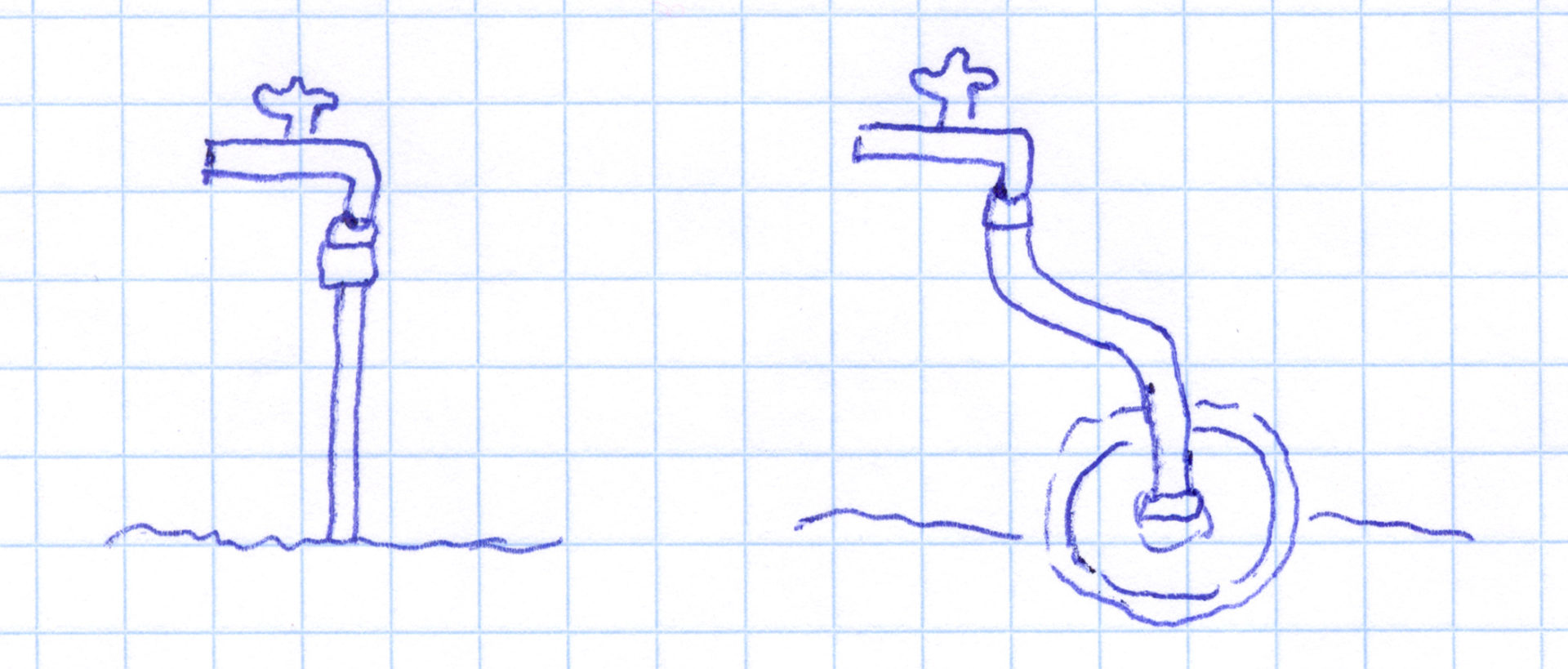
On the left direct connection of the pipeline pipe with a connector to the water tap, on the right connection via a tap connector, a hose connector, a short piece of hose and another hose connector and tap connector to a junction box from which the pipeline leads away.
Recommendation: don’t do that! Suitable for testing irrigation during assembly, but not for ongoing operation. Apart from the fact that in most cases you will not get by with just one sector, you also completely block the outside water tap or the pump for other things.
2. Installation of locks
Like previously described. Here, too, the control is completely manual, but locks accessible from above are provided in the pipeline with the help of shut-off sockets or extension pieces with ball valves. If necessary, these can be opened or closed with a rotary movement and thus individual sectors can be switched on and off in a targeted manner. So, for example, you first open the lock for sector 1. After 1/2 hour you close it again and open the lock for sector 2.

Control with locks
Recommendation: Worth considering if you want to avoid electronic tools but still want to run several sectors. Especially if there are only a few sectors. Disadvantage: You always have to activate and deactivate the sectors manually. A water supply in absence is not possible.
3. Use of a manual water distributor
In this variant, a water distributor is connected directly to the water tap or the pump. These are usually available as 2-way or 4-way distributors, i.e. with 2 or 4 outputs. The outputs can each be regulated and locked with a rotary switch. The control is completely manual. If you need more than 4 outputs, you can also combine the distributors, e.g. connect two 4-way distributors to the two outputs of a 2-way distributor. In such cases, however, not directly but connected with a short piece of hose. This should not be mounted hanging freely, but supported, to avoid damaging the outside water tap. The outlets of the distributor are either connected directly to the pipeline pipe (variant 1) or, as described in point 1), routed via a flexible hose into junction boxes or to the pipeline pipes (variant 2).
A third, even nicer variant is not to connect the water tap directly to the distributor, but to lead the water into a distributor box via a flexible hose (variant 3). In the distributor box, the hose is either routed directly into a manual 2-way or 4-way distributor and from there the pipeline pipes are fed out of the box again. Or you can make your own distributor using a valve distributor tube and manually controllable connectors with ball valves, then you can dimension it larger with any number of sector outputs.

Sketch for variants 1, 2 and 3 (from left to right)
Recommendation: A possible alternative to the solution presented in point 2. This is easier to implement and can be adjusted relatively flexibly if necessary. Apart from the last variant mentioned, the implementation costs are also lower, especially if there are a larger number of sectors. Small disadvantage: Variants 1 and 2 may be a little less elegant than the virtually invisible locks. Tip: It is best to always plan for one more exit than necessary, so that there is a free exit through which you can drain water from the tap as normal.
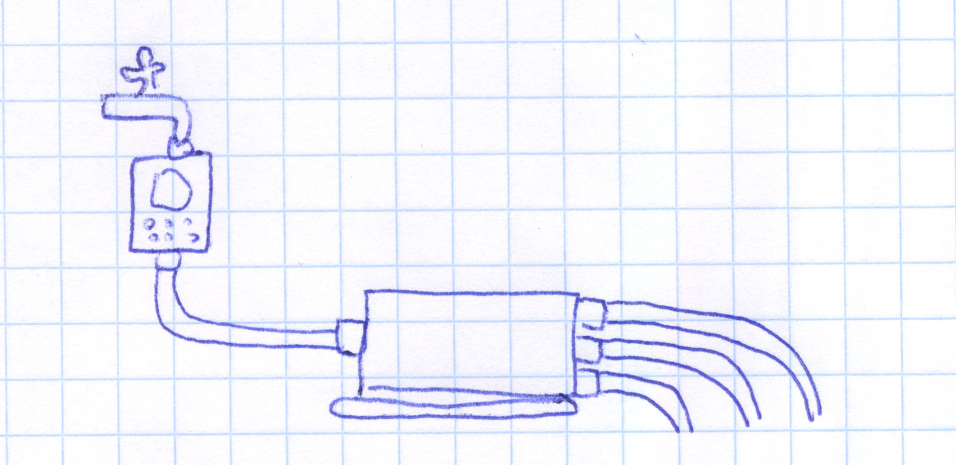
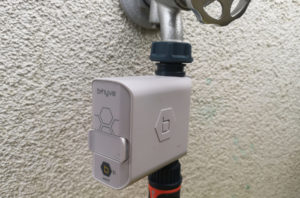
4. Connection of faucet and pipeline via an irrigation computer
The structure corresponds to that described in point 1: The outside water tap or the water pump is therefore connected directly to the pipeline (connected directly to the pipe or via a junction box). However, an irrigation computer is now installed between the tap and the pipeline. In this case, the water tap is always turned on and the water pump is always on standby. The irrigation computer can be programmed to open its valve and allow water to enter the pipeline. And also when to close it again. This enables automatic control of the irrigation. The usual irrigation computer has an output so it can be used for irrigation with one sector. There are also models with 2 outputs, with which automatic control of 2 sectors is possible.

Irrigation computer with one output or 2 outputs
Recommendation: If you only have one or a maximum of 2 sectors, this is a very practical solution. Recently there are even models with 3 or 4 outputs. You can automate your watering and you don’t have to think about it anymore or you can go on vacation for 2 weeks without worrying. The costs for the computer are manageable, but vary greatly. Therefore: compare prices! If you have more sectors and would like to automate then continue reading points 5 and 6!
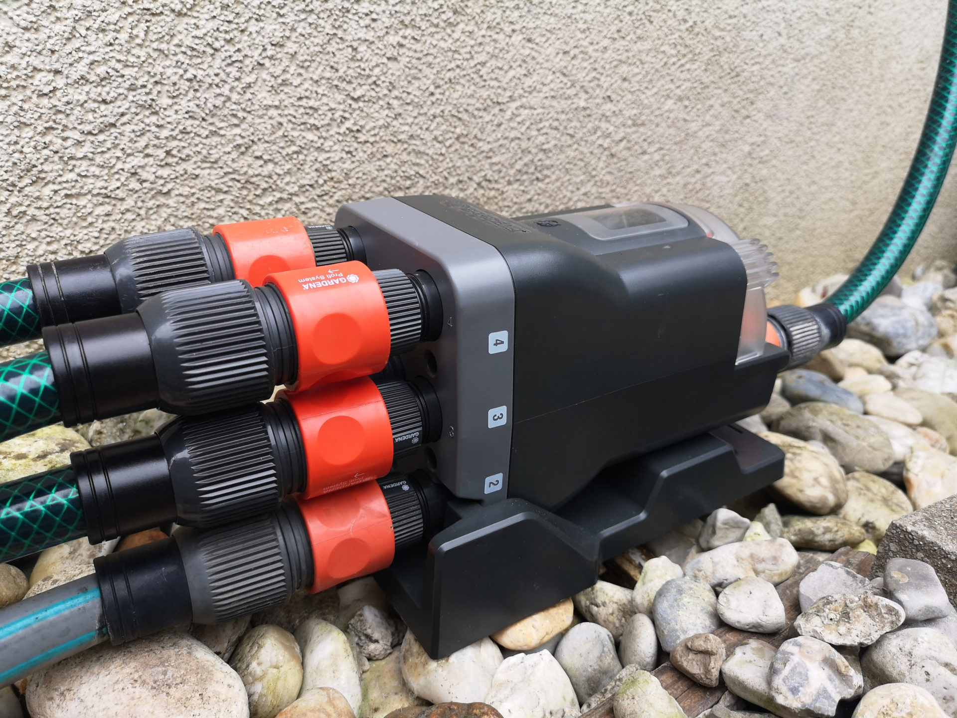
5. Control with irrigation computer and automatic distributor
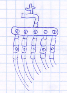
As in point 4, the water tap or pump is connected to an irrigation computer. However, its output does not lead directly into the pipeline, but to the automatic water distributor. This has six outputs, each connected to a sector of the pipeline. The exits are automatically run through in a circular fashion one after the other. Switching from one output to the next happens purely hydraulically without electronics: after the watering computer has been started, water flows through the first output of the water distributor. As soon as the planned watering time has expired and the water computer closes the valve, i.e. no more water flows, the pressure at the outlet of the water distributor drops. This drop in pressure triggers a mechanism that automatically switches to the next output. In this way, after the end of each watering run, the next output and thus the next watering sector is automatically switched to. Switching on can take a few seconds, which is why a small time buffer should be planned between the individual watering runs.
At the moment, despite intensive research, I only know of the automatic water distributor “automatic 1197” from Gardena, there doesn’t seem to be any competing products here – possibly due to patent protection. The predecessor product (“1198”, looks a bit like a flying saucer) is also sometimes offered.
With the automatic watering computer, it is possible to implement fully automatic watering with up to 6 sectors.
The water tap is connected to an irrigation computer, which leads on to the automatic distributor. Up to 6 sectors can be supplied from there.
Recommendation: In professional solutions, solenoid valves are practically always used (point 6), but from my point of view, the solution with the automatic water distributor also works perfectly for private users. One advantage is that this purely mechanical solution does not require electricity or batteries, so you save on running electricity and battery costs as well as laying cables. In addition, the implementation for beginners is simpler compared to the solenoid valves. The costs are also lower, since each valve has to be purchased individually for the solenoid valves and there are also costs for the valve box, pipe distributor and connector.
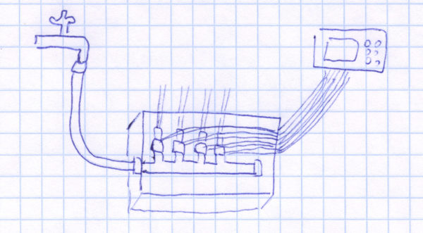
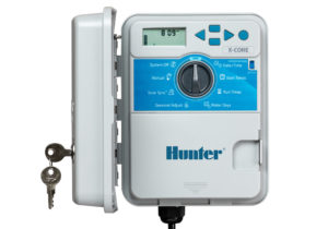
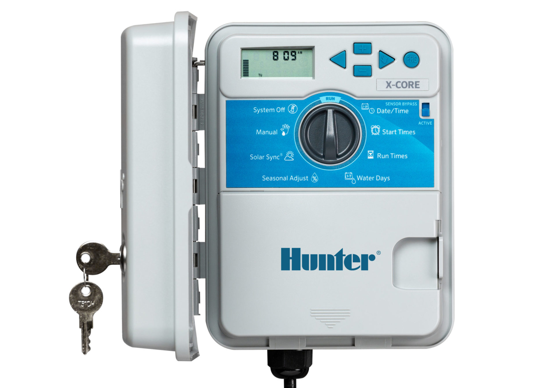
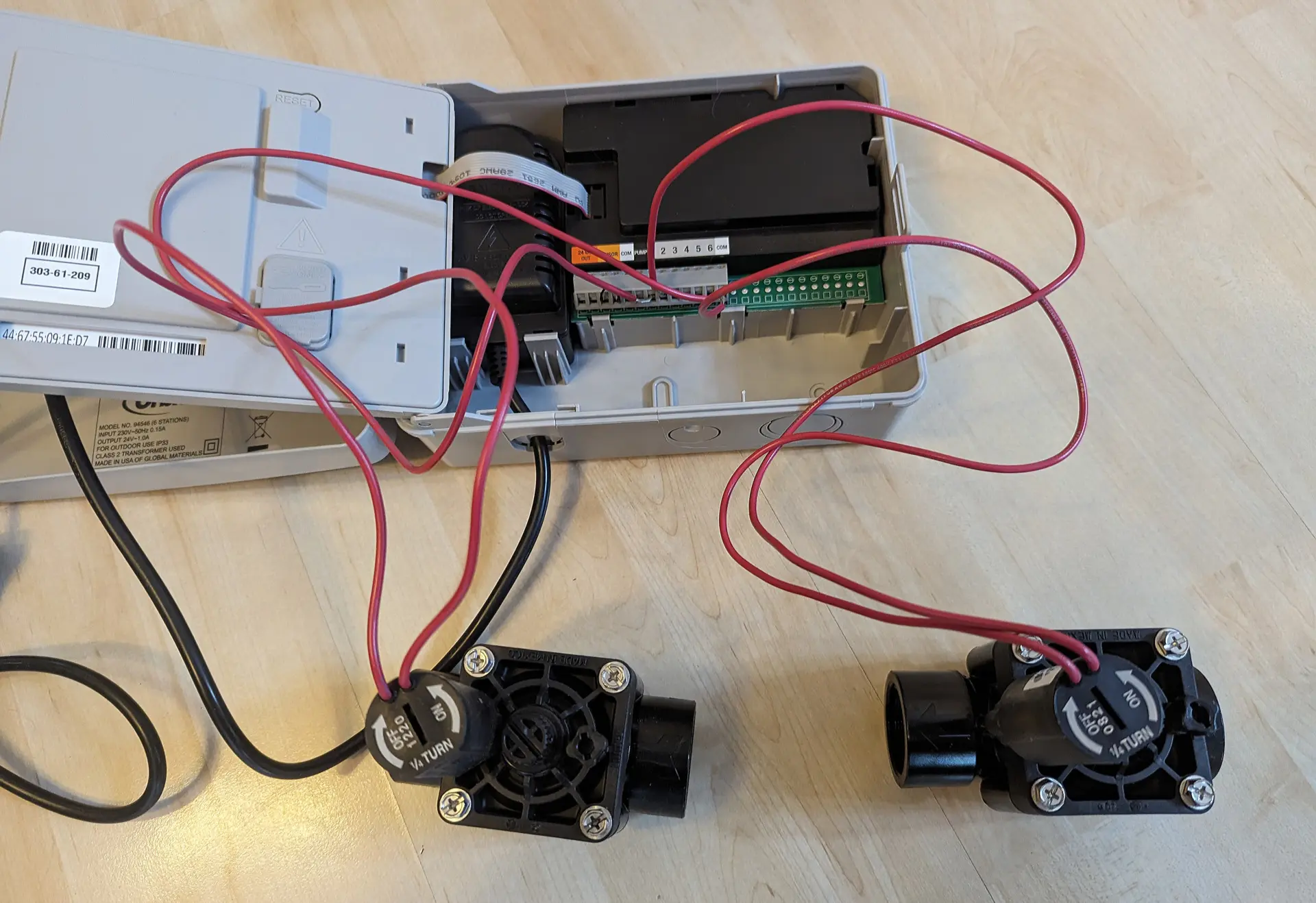
6. Control with irrigation computer and solenoid valves
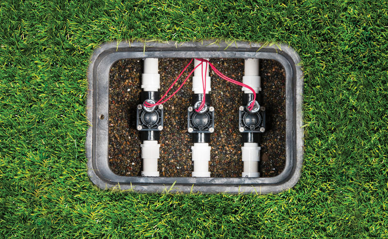
With this variant there is no direct connection between the tap/pump and the irrigation computer. Instead, the water source is connected directly to the solenoid valves. The most convenient way to do this is via a valve box in which the solenoid valves, which function like sluices, are installed. They let the water through to the desired sector on command. In order to receive this command, each valve is connected to the irrigation computer via a cable connection. This is a different type of irrigation computer than that described in the previous points. The water does not run through the computer here, but the computer is used purely to control the opening and closing of the solenoid valves. To do this, a short pulse is sent to the solenoid valve via the cable connection. Depending on the computer model, 4, 6, 12 or even more solenoid valves can be connected to the computer.
You can find out more about how the solenoid valves work, what different types there are, what to look out for and what types of control there are in the next point “Control with solenoid valves”.
Recommendation: The use of solenoid valves is the most professional and flexible type of irrigation control, which gives you many options, including with regard to possible integration into home automation (smart home). The use of valve boxes (valve shafts) is comfortable and chic, but not exactly cheap. If you do not want to afford this luxury, you can assemble such a box yourself or alternatively mount the valves on a wall.
Control with solenoid valves
Below is an overview of what needs to be considered when controlling with solenoid valves and what different options you have here.
Battery or electricity powered
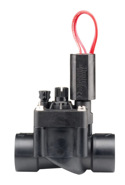
There are basically two types of solenoid valves on the irrigation market:
- 24 volt solenoid valves
- 9 volt solenoid valves
The 24V valve is the most common standard valve. In order to be able to use it, the irrigation computer must be connected to the electricity. The power line is routed to the computer, in which a 24V transformer is installed. Cables with 24 volts then run from the computer to the solenoid valves, two of them per valve. The 24V valve works with alternating current (AC). For special cases, e.g. if you want to control the valves directly via the home automation (smart home) and this control uses 24V direct current, 24V direct current valves are also available.
If a power supply is not possible and the irrigation computer is therefore only battery-operated, then 9V valves should be used. 9V valves work with direct current (DC). If there is the possibility, one should always prefer the standard 24V variant used in the professional sector to the 9V valves, the 24V valves are also significantly cheaper than the 9V valves.
Low flow capable or not
The valves require a certain minimum flow rate to function properly. This is because the solenoid valves used in garden irrigation are so-called pilot-operated valves that use the pressure of the water to open and close. Normally this is not a problem. However, if there are only a few consumers in a sector for micro-irrigation, i.e. only little water is used, it can become one. In this case you can use valves that are also low-flow capable or go straight to special valves for low flow. These already work with a flow rate of about 13 gallons per hour.
With flow regulation or without
This means the possibility of narrowing the flow at each valve if necessary and thus controlling the amount of water flowing through. This allows you to adjust the amount of water for each sector individually. This can be useful if the pressure is already too high in principle (instead of using a pressure reducer) or if significantly less pressure is required for a micro-irrigation sector. Or if you want to shorten the throw distances of all sprinklers in a sector at once – without using the sprinkler screw.
Mounting on the floor or on the wall
Solenoid valves can either be mounted lying on the floor or hanging on a wall. Horizontal assembly is usually in a valve box or other container that serves the same purpose. It is important that air gets to the valves, as no condensation should form. Installation in a closed sack or similar is therefore not recommended, as the valves will then break more quickly! Apart from that, you should be able to reach the valves with manageable effort (removal in winter, maintenance). There are specially designed valve manifolds for mounting on the wall, but you can alternatively put together such a device yourself relatively easily. A cheap option is to mount it directly on the outlets of a manual water distributor.
A cost-effective option is to mount the solenoid valves directly after the water tap, on a manual distributor
Further link: In the following blog post you will find a manufacturer-independent overview of the solenoid valves available on the market
Irrigation controller
There are two completely different types of watering computers, each of which can only be used for the intended purpose:
- Sprinkler timer through which the water runs
- Irrigation computers that control external solenoid valves
Sprinkler timer through which the water runs
The watering computers of this type are basically just computers with a built-in valve (or two or more in some models). As soon as a certain event occurs, e.g. the programmed weekly watering starts, the computer software opens the valve and the water can flow through the water computer. As soon as another event occurs, e.g. the end of the programmed watering, the computer software closes the valve again.
Further link: Performance data comparison of sprinkler timer through which the water runs
Irrigation computer for valve control
This second type of computer does not come into contact with water. It is used to open and close solenoid valves. So not the valve built into the computer as in the first case, but magnetic valves outside the computer. To do this, the solenoid valves are connected to the computer with cable connections. The software itself basically works like the previously described type of watering computer, except that when the event occurs, the valve is not opened directly in the computer, but instead an impulse is sent via the cable connection to the connected solenoid valve, which then opens or closes.
Further link: Irrigation computer for valve control in comparison
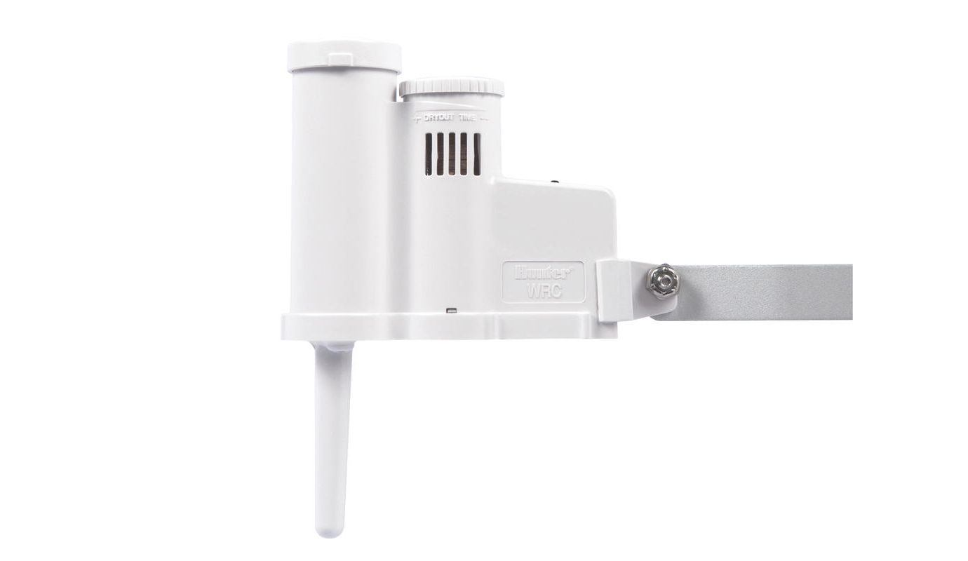
Sensors
The use of sensors offers additional options for controlling irrigation or further automating the control. The sensors measure certain properties and report either the measured values themselves or an impulse resulting from the measured values to the irrigation computer. There is a very large range of different sensor types for irrigation computers for solenoid valve control, but for irrigation computers through which the water runs, the selection is rather limited.
Sensors are connected to a sprinkling computer either by cable or wireless connection, usually connections for 1 or 2 sensors are provided. For private use, the following sensor types are most important:
- Rain sensors
- Soil moisture sensors
- Multiple sensors (e.g. combination of rain and frost sensor or combination of rain, frost and water evaporation sensor)
Rain sensors prevent irrigation if a specified amount of rain has fallen in a certain period of time. Some rain sensors also have an additional function that immediately switches off irrigation that is already running as soon as it rains. Soil moisture sensors measure how moist the soil is in the root region of the lawn or other plants. If it is still moist enough so that no watering is necessary, then this is prevented. Multiple sensors combine multiple sensors in one device. A very popular example of this type in practice is the Hunter Solar Sync, which includes both a rain and frost sensor, as well as additional sensors for measuring temperature and sun intensity. Based on this, it extrapolates the water evaporation and adjusts the irrigation duration based on this.
In the following blog post you will find a more in-depth introduction to the topic of sensors.
Methods of control
Here are some ideas for ways to design your controls:
- Manually start watering runs when needed.
- Periodic repetition of one or more programmed watering runs (e.g. weekly every Monday from 08.00 to 08.30 am sector 1, from 09.00 to 09.15 am sector 2).
- Programming of an individual weekly program for each sector (sector 1 on Monday from 09.00 to 09.15 am and on Thursday from 01.00 to 01.15 pm, sector 2 on Tuesday from 08.00 to 08.30 am).
- Programming of irrigation runs that are suspended when a sprinkling or soil moisture sensor gives the appropriate signal.
- Programming of irrigation runs, the running time of which is reduced when an evapotranspiration sensor indicates that the weather conditions allow it.
- Programming of irrigation runs that are suspended or whose runtime is reduced if the data from a weather service connected via the web provide the appropriate input
- Programming of watering runs depending on other events in the home automation, such as driving the automatic lawn robot. And vice versa: For example, only let the automatic lawn robot drive when the watered lawn has dried again.
- Have irrigation completely controlled by a smart irrigation computer. On the basis of weather observations and data stored once about the garden, this decides independently whether it will be irrigated, on which days it will be irrigated and for how long it will be irrigated.
- As before, but use data for the weather observations that were measured using your own private weather station.
This is how the Gardena 6-way automatic water distributor works
Despite all the skepticism I have about some products from the German brand Gardena, especially about the sprinklers, I am an all the bigger fan of the Gardena water distributor automatic. How to use this [...]
Solenoid valves for garden irrigation – which ones are there and how do they differ?
In this blog post you will find an overview of the solenoid valves available on the irrigation market and their performance data. You will also find out which functionalities are important for you as [...]

Comparison of the sprinkler timers available on the market
Purchasing a sprinkler timer is not as easy as one would expect: It takes a lot of time to compare the products available on the market, because many sales offers only give part of [...]
Irrigation computer for valve control
This article is about irrigation computers for controlling solenoid valves. The most important models available on the market are presented and explained what distinguishes them from one another and what criteria to look out [...]
Rain, soil moisture and other sensors
Sensors give you the ability to dynamically adjust irrigation to local conditions. On the one hand, this allows irrigation to be perfectly tailored to the requirements of the lawn and plants, and on the [...]
How to connect solenoid valves to the irrigation computer
In the following article I explain how to connect solenoid valves to the irrigation computer and what you need to bear in mind. At the end of the article I will discuss the special case [...]