In this blog I have already presented two free online tools for planning garden irrigation: the DVS irrigation planner and the myGarden planner from Gardena. Unfortunately, the former is currently only offered in German language and the latter in English but only in the metric system of measurement. The online irrigation planner from the US irrigation manufacturer Orbit, the Orbit Sprinkler System Designer, is currently the only free online planner in English and in imperial measurement that I know of. I tested this one. You will find out below whether it is a serious alternative to the two previously mentioned and what it can do better or worse.
The Gardena myGarden planner has been around for many years, the German-language planner from the online irrigation web shop DVS Beregnung went live in 2020 and, in my opinion, is currently a step ahead in terms of quality. Both are web-based and can be easily run in the web browser without downloading any software. This also applies to the planner from Orbit. Orbit is a manufacturer of irrigation products with a sales focus on the USA, but is also known outside the USA primarily for its irrigation computers. In 2021 Orbit was taken over by the Gardena parent company Husqvarna and integrated into the German garden and irrigation company Gardena.
The Orbit Online Planner only caught my eye a few months ago, but from my research it seems it has been around for a few years. On the web you can find the first descriptions and videos of the orbit planner dating back to 2011. However, the online planner shown in the videos does not correspond to the one that is currently available on the web. That in itself wouldn’t be anything out of the ordinary. Then they would have developed the planner further, was my first thought.
Strangely enough, however, it is exactly the opposite: what is currently available on the web seems like an incomplete and less user-friendly preview of what can be seen in the videos. I can’t explain it logically and I haven’t found any information as to why this is the case. The only reasonable explanation I can think of is that for some legal reason the original version was no longer allowed to be used and that it was then programmed again in a significantly simplified way, optically slimmed down and provided with fewer details. What is offered looks like a rather listlessly created quick copy of the previous version.
And that brings me to the big point of criticism of the Orbit Designer: The tool is extremely user-unfriendly! I haven’t seen anything like this on the web for a long time, something like this was more normal in the early days of the World Wide Web. Basically, everything works, but the software is not intuitive to use at all, things don’t work the way you’re used to and in some places you have no idea how to proceed and can only figure it out by trying it out for a long time.
So why am I introducing the Orbit Irrigation Planner at all? Because the basic functionality is basically quite good and also surprisingly extensive. Those who designed it originally went to work very ambitiously and also built in options that are currently not available with the other two designers, e.g. that you can, if you want, specify exactly how a certain micro-irrigation area should be watered , e.g. with drip irrigation, spray irrigation or together with normal lawn irrigation. So once you find your way around, the planner can definitely be of good service to you and may offer you functionalities that you miss elsewhere.
In the following I describe the essential steps in the use of the planner. This is also a good opportunity to look it up if you get stuck somewhere.
Start with a blank sheet of paper or with an existing property plan
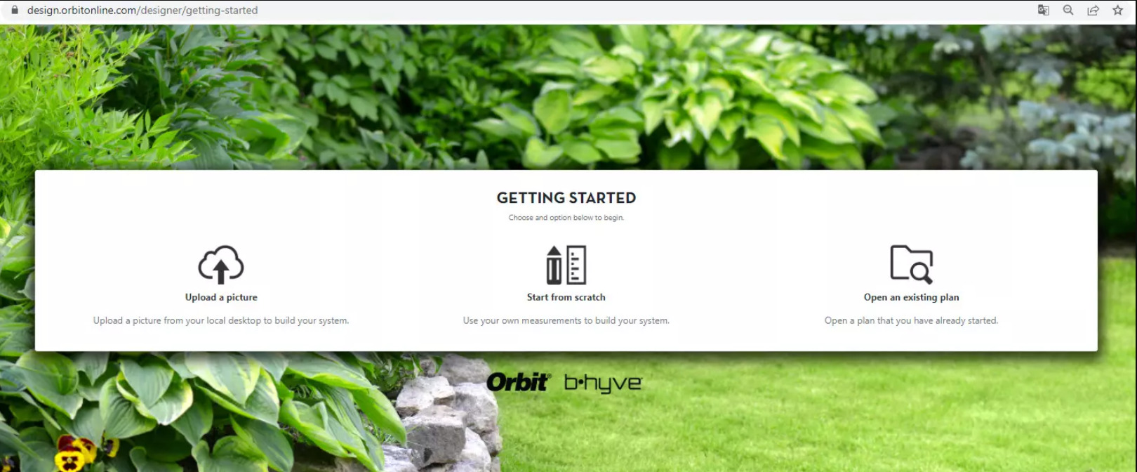
The beginning works in a similar way to what is already known from the competitors: You can either start from scratch or you can load in a sketch you have made yourself or a property plan and use this as the basis for further planning. If you have already created a plan in the software, you can continue with this as a third option.
Orbit Designer home screen
The first and the second point, i.e. starting with an image of a property plan or starting with a blank sheet of paper, basically do not differ from what follows. In both cases, you load the same planner, except that a different submenu is opened at the start.
menu and navigation
A four-level menu tree is displayed on the right-hand side with the following main items:
Property
Watered Areas
System
Report
Step 1: Draw the plot to be irrigated
Below is a description of the steps in which you can create a plan of the property to be irrigated.
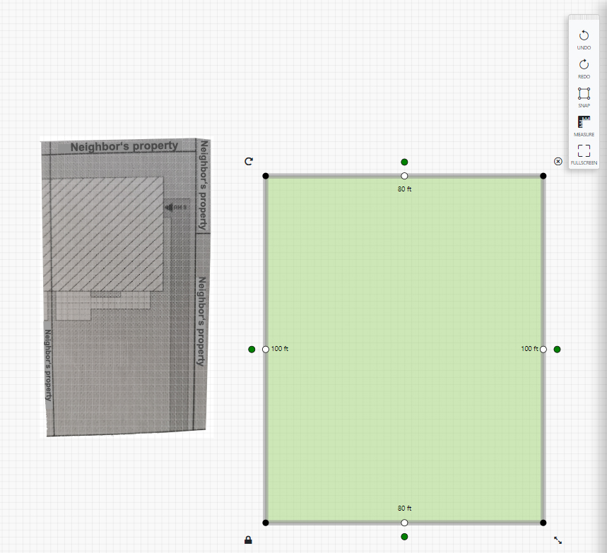
Load property plan and define scale
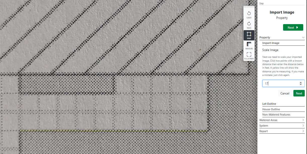
If you want to import an image of the property, select the “Import Image” sub-item under Property and select the desired image file. Right after that, you have to tell the system the scale of the uploaded image. You do this by defining a straight line on the uploaded image with two mouse clicks and then telling the system what distance this straight line corresponds to.
For example, you could draw a straight line across the width of the garden and then enter that value. Attention: This didn’t always work for me right away in the test, especially when the property plan was quite large, it happened that I couldn’t draw the straight line over an entire width, but a shorter distance worked.
Look closely: The straight line is shown in a very light yellow that is not easily visible!
Enter the distance in feet. Note for readers from countries with the metric measurement system: 1 foot equals 30.48 centimeters. For example, a distance of 10 meters would be 32.8 feet.
Here the floor plates in the lower area were used to define the scale (the yellow scale line is only faintly visible). Each plate is 1.64 feet wide, so the ten plates marked with the straight line are 16.4 feet wide. Since only whole numbers can be entered and because there is a small distance between each plate, I round up to 17 feet (see entry in the box at right).
After loading the image, you can rotate it under “Orient Image” if necessary.
All other points work the same, regardless of whether you have loaded an image of a property plan or draw the plan from scratch.
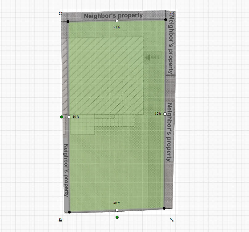
Define the outline of the property
This point gave me some headaches at first, because it is handled differently in the other tools I know and is not explained anywhere in Orbit. You cannot draw the areas to be irrigated piece by piece here, because otherwise the further planning will not work. Instead, the maximum outline of the property must first be defined in a contiguous area. And then you subsequently exclude those areas that should not be irrigated or define areas that should be irrigated in a different way.
The outline is defined in the “Lot Outline” menu item. There you first click on the displayed lawn icon and can then decide in the tool menu whether you want to place the outline with the freehand tool or in a square shape.
If you select the square shape, you then have to click on the plan and a lawn square will be placed there. This can then be brought to the desired size by dragging the corner points.
If you are working from an image template, then the next step would be to place the outline over that template
The padlock icon at the bottom left of the square locks the selected object against movement. So if you want to place it somewhere else, you first have to click on this symbol to open the lock. If you want to delete an object, this does not work with the Del or backspace key on the keyboard, but you have to click the cross-delete symbol at the top right of the object. Executed steps can be undone by clicking on “Redo” in the toolbar.
In my example with an existing image of the site plan, I defined the outline with the freehand symbol. To do this, simply start at a corner of the image template and click on it, then move the mouse pointer to the next point and click on it again. This is repeated until you have defined all corner points. You don’t have to single-click the last corner, but double-click to complete the outline creation! This is also not described anywhere and is not evident from anything, so that it is difficult to come up with it yourself.
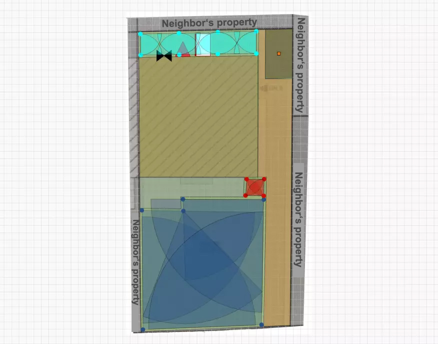
My example plan after drawing the property line with the freehand tool
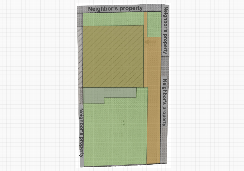
Draw in the house and other non-irrigated areas
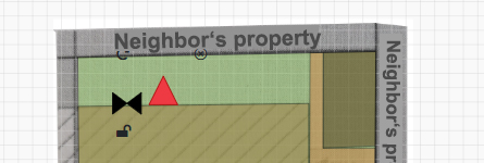
This is done in the two menu items “House Outline” and “Non-Watered Features”. The way it works is the same as described above, so you can take out the areas that are not to be irrigated either as rectangles or in free form. In my case, I draw these with the freehand tool as well. I simply draw over the existing lawn outline.
The house, terrace and path to the house have been added
Step 2: Define additional areas to be irrigated
Namely, areas that are not lawns, because this one has already been drawn in. But those areas that should usually be watered more gently and slowly with drip irrigation, such as beds, flower pots, bushes, hedges or trees. Or even those that are to be watered with nozzle spray sprinklers with a very large water flow. In my example case, I draw in a vegetable patch.
The vegetable patch was added in dark brown at the top right
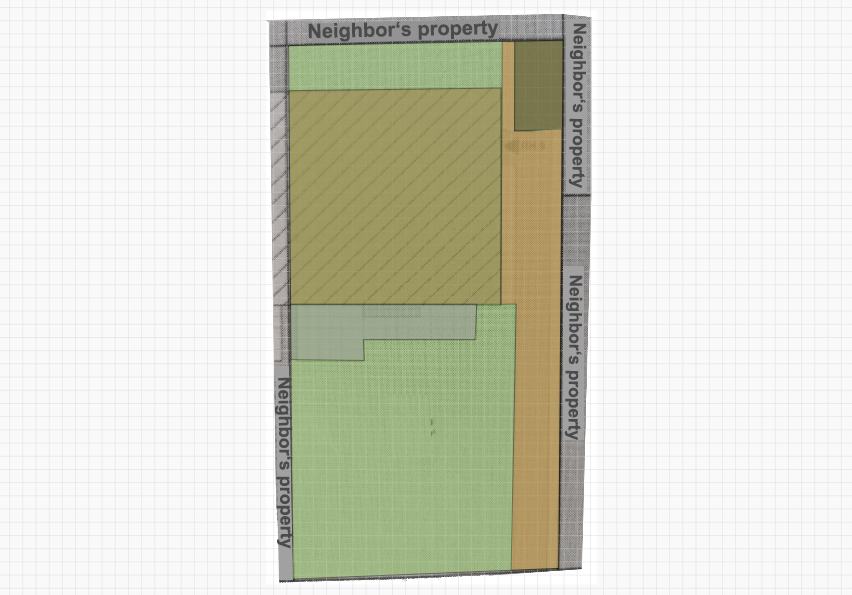
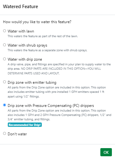
After drawing in the desired type of irrigation for the area is to be determined. The system also makes a suggestion here. In my example, this is drip irrigation for the vegetable patch.
Determination of the desired irrigation type for the marked area
Special areas to be irrigated
In the sub-menu item “Special Watered Areas” you can now take the planning to the top and specify to the planner whether you would rather irrigate an area with ordinary geared sprinklers or nozzle sprinklers or rotating nozzle sprinklers. Depending on the choice, the planning is then carried out with the selected sprinkler type. On the one hand, this is a great feature that no other online planner I know of has, on the other hand, it could be a little overwhelming for one or the other user. In this case, you can safely leave it out and try the standard planning first!
3. Placement of system components and entry of system performance data
In this step, the missing information that the system needs for planning must be added.
Placement of system components
Here you have to define where on the plan the connection to the water supply is located and where the irrigation computer is to be installed. Optionally, you can also plan a rain sensor and empty piping for later additions to the pipeline. Placement is the same as in the previous steps: click on the icon and then click again on the spot on the plan where you want to place the component.
In the example, the water supply and the irrigation computer are planned behind the house
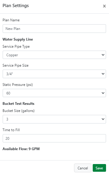
Input of key data for performance determination
The following key points must be entered so that the system knows what water pressure and available water volume it can plan with:
Diameter and material of the water supply line
Static pressure at the water connection used
Maximum amount of water available according to the bucket test
How to determine the available amount of water according to the bucket test, I describe here in the blog in a separate blog post. This is always the maximum range in which you move, since the water flows out without resistance in this test. In an irrigation system, however, considerable resistance has to be overcome and pressure applied to rise the sprinklers, and the actually usable amount of water is therefore significantly lower in the end. The orbit planner calculates this automatically.
The same applies to the static water pressure at the water connection. This forms the maximum frame, but cannot be completely exhausted in practice. But you don’t have to worry about that either, because the system automatically takes this into account. In the following article I explain how to measure this static water pressure.
The diameter of the water supply line means the diameter of the pipe through which the water is led from the water supplier to the house, i.e. the pipe that leads to the house on the street side. If you are not sure about the diameter of the pipe, you can measure the circumference by stretching a thread around the pipe and then determine the pipe size based on the measured circumference. Since the pipes have different wall thicknesses depending on the pipe material used, the determination depends on the material:
Enter the pipe size in inches determined in this way and the material from which the pipe is made into the mask. From these values as well as the static water pressure and the available amount of water according to the bucket test, the system calculates the capacity available for irrigation, on which the subsequent irrigation plan is then based.
Key performance data input for my planning example
Placement of solenoid valves
After clicking on “Place Manifolds” the system automatically calculates the number of necessary solenoid valves. You can then also place them on the plan.
Step 4: Generation of the irrigation plan
To do this, simply click on the “Generate Design” button and the Orbit Sprinkler Designer will create a complete irrigation plan based on the drawn property plan, the defined irrigation areas, the placed components and the system information. In my example it looks like this:
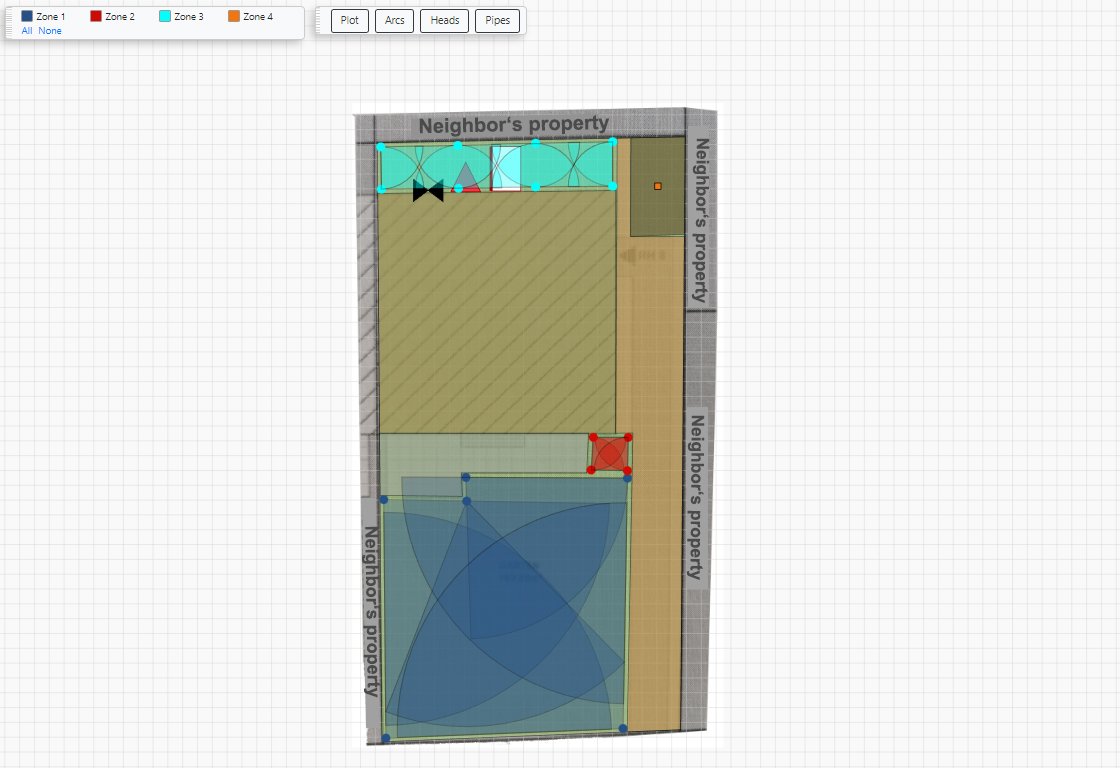
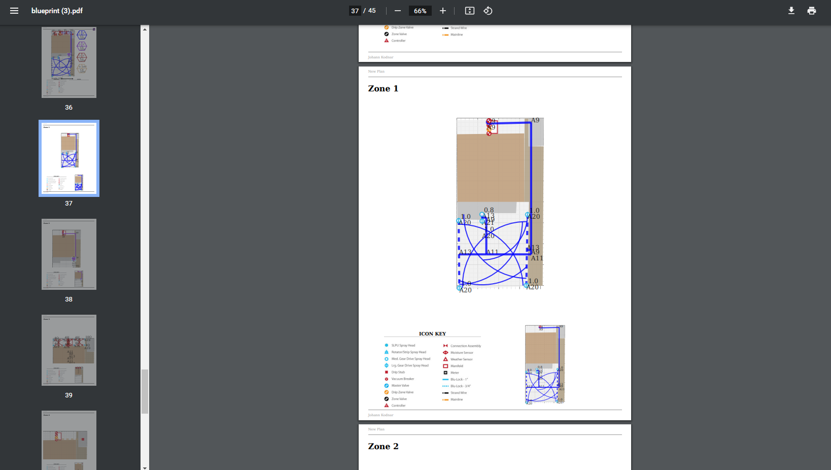
Created irrigation plan with irrigation arcs
At the top left there is a control bar with which you can limit the display to specific zones. In my case, the automatic system planned 4 zones to be watered. By default, the irrigated areas are displayed with arcs. Based on the intensity of the color you can see which areas are poured more and which less overlapping. Alternatively, you can switch to a sprinkler view and a pipeline view.
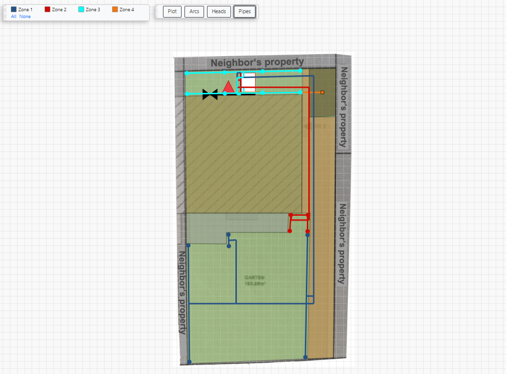
Pipeline view
In contrast to the online planners of the competition, you cannot manually intervene in the automatically created watering suggestion of the system. From my point of view, the auto-plan created in my example is qualitatively okay, correctly created according to the principles of the square formation. Presumably due to the limited range of sprinklers from Orbit, it is partly a bit coarser, with fewer sprinklers, than the planner from competitor DVS Beregnung.
List of required components and installation plan
After clicking on “Parts List” you get a list of all the parts required to put the watering plan into practice. Only products from the Orbit Universe are suggested here in the Orbit Planner, but of course you are free to replace the suggested products with other brands. This is comparatively easy with some components such as pipelines, solenoid valves and connectors, but you have to be careful with the sprinklers, as there are greater dependencies here and the suggestion made will most likely no longer fit if you choose a different sprinkler model.
The extensive installation instructions, which you can download as a PDF file after clicking on “Download Installation Guide” again, are very practical. This contains step-by-step instructions for the practical implementation of the irrigation plan.
I am an enthusiastic do-it-yourselfer and have been running this blog on the subject of garden irrigation for more than 6 years now. In over 150 specialist articles, I share my own experiences and know-how from years of research and numerous product tests. -> More about me


")


